A permanent solution at Salt Springs dam
14 March 2006Based on the construction history and experiences from the past performance of Salt Springs dam, concrete repairs made to the dam face have been unable to accommodate continued movement and settlement of the structure. As a result PG&E and its independent board of consultants decided that installation of a flexible membrane over the existing concrete face would more satisfactorily provide the desired leakage control and accommodate any future settlement
Salt Springs, owned by US-based Pacific Gas & Electric Co (PG&E), is the fifth oldest concrete faced rockfill dam (CFRD) in the world and the first CFRD to reach 100m in height. It is located in California, south and east of Sacramento, high in the Sierra Nevada Mountain range. In the 1930s, construction of the dam was halted at mid-height and when the rock placement resumed the sluicing technique was improved. This created a zone of differential settlement in the dam where the concrete face has required continual repairs over its 70+ year history. In 2001, a significant crack in a face slab in this zone resulted in a significant increase in seepage. To permanently fix the upstream face, PG&E selected an exposed PVC geomembrane system. In 2004 the system was installed in the most deteriorated area. The installation was completed in the spring of 2005 encompassing 18,500m2 on the face of the dam.
Salt springs dam
Salt Springs CFRD was constructed from 1928 to 1931, extending from el 1106 to 1206m asl. The initial construction procedure consisted of placing dumped rock in a lift approximately 52m high at its maximum, up to about el 1158m. Because of the large lift and rock placement techniques, the materials tended to segregate with larger boulders (40,800kg) generally at the bottom and smaller boulders (2700kg) on top. This resulted in poor consolidation that was soon recognised by the large settlements measured during the first year of construction. Subsequently, the rock placement that followed in the remaining two years (1930 and 1931) of construction was changed. Lifts were reduced to about 23m in height and significantly more water was used for sluicing the materials to achieve better consolidation.
The initial rock placement procedures, however, left the dam with an inherent settlement problem that has necessitated numerous concrete face repairs over the decades, primarily along the abutments and the transition zone at el 1158m. These repairs have included 10-15cm thick shotcrete overlays, several thousand square meters in area.
In the spring of 2001, a significant horizontal crack developed across one of the 18m wide face slabs that increased leakage as measured at the toe weir to over 1130 l/sec with a water surface elevation of only about 1164m. Divers made emergency repairs.
In early 2002 with the reservoir level down below the transition zone, extensive concrete repairs were made across the entire transition zone between elevations 1155m and 1161m. With the spring runoff filling the reservoir (normal maximum water surface – 1206m), leakage reached 850l/sec, the limit established by the Federal Energy Regulatory Commission (FERC) and the Department of Water Resources, Division Safety of Dams (DSOD).
In early 2003 interim joint repairs were performed from about elevation 1158m to the crest of the dam (el 1206m). Leakage with a full reservoir peaked at 760 l/sec, about 10% less than the year before.
In March and April 2003, concurrently with the joint repairs, PG&E Technological & Ecological Services (TES) performed an assessment of the existing concrete face. Surface scaling due to freeze-thaw action was observed, but generally there was no significant freeze-thaw deterioration. The concrete slabs appeared to be in good condition for concrete that was placed over 70 years ago.
While the assessment determined that the average concrete strength of the cores was very good, the impact-echo wave speed velocities were generally favourable, and the freeze-thaw deterioration was fairly limited; numerous pockets of honeycombing at cold joints were observed across the face slabs. Unlike the concrete placement of face slabs on other rock fill dams constructed in the early 1900s, no separation barrier (e.g. tar paper) was installed between the underlying placed rock and the concrete face slab. This lack of a barrier contributed to the segregation of cementitious materials at their time of placement, resulting in the loss of cement paste around the aggregates, honeycombing and uneven consolidation. These areas were probable or potential paths for leakage.
History of face repairs to address leakage
Based on various reports on the construction history of the dam, including a well documented 1958 report (see references) by I.C. Steele and J.B. Cooke, settlement of the dam, especially in the main construction lift of el. 1158m, had caused repeated cracks to the upstream face over the ensuing years. In addition to the 2001, 2002 and 2003 repairs, previous repairs to the concrete face slab have been reported in 1938, 1941, 1944, 1946, 1948, 1949, 1953, 1954, 1955, 1958, 1962, 1964, 1966, 1968, 1972, 1979, 1980, 1982, and 1995. Each of these prior maintenance repairs involved concrete patching, concrete overlay, joint repairs, and/or joint sealant. While the concrete repairs over the last 70 years have controlled leakage, they have been plagued by the same settlement problems that confounded the original engineers who designed the dam.
Based on the construction history and experiences from the past performance of the dam, concrete repairs made to the face had been unable to accommodate continued movement and settlement of the dam, especially in the el. 1158m transition zone. The continued attempt to use a rigid material (concrete) had not provided for a long-term repair solution. Since the face slabs served as a water barrier for the dam, PG&E and its independent board of technical consultants decided the installation of a flexible membrane over the existing concrete face would more satisfactorily provide the desired leakage control and also accommodate any future settlement of the dam.
Subsequently, PG&E began to investigate how to permanently fix the upstream face at Salt Springs. Their initial conclusion was to install a PVC geomembrane system over the upstream face above the transition zone with the goal of reducing the seepage to 340 l/sec. In the spring of 2004, the carpi geomembrane system was installed over the center of the face to cover the transition zone (Phase 1 – 1155m to 1161m elevations) and to mitigate against seepage from the type of concrete slab cracking that had occurred in 2001. The geomembrane system successfully arrested seepage across the zone during the filling of the reservoir from snow runoff in 2004.
At the same time, PG&E hired engineering firm Gannett Fleming to perform a seepage analysis of various geomembrane configurations. The analysis results showed that in order to maximise the seepage reduction from a geomembrane installation, the area of the geomembrane system installation should be altered and extended down the face, instead of to the crest. Accordingly, the geomembrane installation plan for Phase 2 was altered and completed in the spring of 2005, covering approximately 18,500m2 on the face of the dam.
Description of concrete face slabs
The upstream face of Salt Springs dam consists of reinforced concrete slabs, about 18m2 on an average slope of 1.3H to 1.0V. The thickness of the slabs uniformly tapers from 30 m at the crest to 90cm at the lowest portion of the toe. Below elevation 1130m, the concrete slabs are covered by a wood facing that is generally underwater.
Between the crest of the dam at el 1206m and the timber facing at el 1130m, there are 21 vertical joints at about 18m spacing. These total 1387 lineal meters. Across the face of the dam are seven horizontal joints, totalling 1606m. The vertical joints were constructed with a copper waterstop and filled with a bituminous coal tar filler.
Seepage analysis
PG&E was interested in estimating the efficiency of the geomembrane system in reducing seepage before undertaking the proposed remediation. Gannett Fleming Inc was retained by PG&E to evaluate leakage/seepage through Salt Springs dam under existing conditions and to predict the leakage after the installation of the proposed geomembrane liner system over the upstream face of the dam.
Historical (Steele and Cook) seepage data and recent leakage measurements obtained during 2002, 2003, and early 2004 were provided by PG&E. The recent data were used to estimate the average effective permeability coefficient of the existing concrete facing for 3m elevation increments. The average permeability of each increment of the concrete facing system was utilised to develop a seepage model for the dam and to predict the seepage versus pool level before and after the completion of each phase of construction. The results of the seepage analyses indicated that Phase 2 rehabilitation would significantly reduce leakage through the dam, for pool levels above el. 1155m.
As indicated by the recent leakage data, the seepage increased abruptly at two pool elevations. The first abrupt change was observed at approximately el 1161m, the second abrupt change occurred near el 1180m. These abrupt changes are indications of significant leakage at or just below these elevations. Other observations reported based on this recent data were that the leakage rate varies by up to 110 l/sec at a given pool elevation and that the early readings from 2004 indicate a trend of higher leakage in comparison to the two prior years. The seepage model was developed utilising the 2002 and 2003 data, as time was not available to incorporate the 2004 data before construction.
After subtracting the estimated foundation seepage at each elevation, from the recent seepage data, a trial and error process was utilised to estimate the average permeability of each 3m vertical increment of the facing system at each pool elevation. (For example, when the pool is at el 1189m, the area between el. 1170 and 1173 contributes 35 l/sec based on the model.) After developing a model that recreated the recent seepage, the geomembrane-lined area was incorporated into the model to provide a predicted seepage after the rehabilitation.
The original liner system limits were planned from el 1155m to el 1206m (top of dam). In performing the seepage analyses, it was obvious that zones contributing significant seepage existed below 1155m. In addition, it was noted that the upper portions of the dam that experienced very little head were contributing minor amounts of seepage in comparison to lower areas. The higher elevations also consisted of the greatest area requiring lining. This evaluation was utilised to identify the alternative liner system limits (el 1146m-el 1192m) actually installed at the site. This alternative liner system configuration resulted in a reduced lined area and optimised the installed square coverage of geomembrane by covering the area contributing the highest incremental seepage. As indicated by the results, the proposed liner system was predicted to reduce the residual leakage to a level well below the established cap of 850 l/sec.
Geomembrane system project details
The original contract for the geomembrane system involved covering the area from el 1155m to 1206m – this being the area just below the transition zone for original sluicing, up to the crest.
Ultimately, the area to be lined in Phase 1 was altered to be el. 1155m to 1161m, due to the record setting warm weather in California in the spring of 2004. This caused an early runoff, filling the reservoir a month earlier than usual.
Based on the seepage analysis described in the previous section, the layout for the area of the geomembrane system was changed for Phase 2. The dam was lined further down the face and area to be lined near the crest was eliminated. This entailed a complete re-pricing of the project as the area below 1155m was less accessible, more perimeter seal involved, and the top perimeter seal had to be converted to a submersible perimeter seal, while the overall area was reduced.
System description
The geomembrane system installation consisted of:
• For the rough surface of the dam, a 2000g/m2 geotextile was placed directly on the surface to smooth the irregularities of the dam face, decreasing surface preparation costs
• 60cm wide Tri-planar geonet along lower perimeter seal for drain collection layer
• Watertight perimeter (stainless steel) batton seal along the left and right abutments
• Watertight perimeter (stainless steel) batton seal at el. 1146m and 1192m
• Drainage plates in each compartment with a drilled hole through the face to allow discharge of water into the rockfill dam body
• Tensioning profiles (stainless steel) installed vertically to hold the geomembrane to the dam every 5.6m
• Geocomposite (PVC geomembrane 2.5mm with geotextile 500g/m2) in 2.1m widths
• Geomembrane (PVC geomembrane 2.5mm) weld strips to cover the tensioning profiles.
Prior to installation of the thick geotextile cushioning layer, geosynthetic material was installed in isolated areas. In these very rough areas or depressions, coupons of thick geotextile and geocomposite as described above were added prior to installation of the 2000g/m2 geotextile layer.
Installation
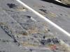
The geomembrane system installation began with surface preparation. The surface of Salt Springs dam was frequently described as a ‘moonscape’, it was extremely rough with craters in the face from deterioration over 70 years of service. Additionally, shotcrete patches had been applied on the face that had offsets of up to 15cm. Originally consideration was given to removal of these shotcrete patches. However, the shotcrete was sound and the cost to remove was prohibitive. The solution was to chip off the vertical edges of the shotcrete patches and then add extra layers of geosynthetic material as added protection, before application of the thick geotextile that was installed over the entire face. The surface preparation took considerable time and represented a significant portion of the overall schedule of the installation.
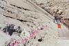
In parallel with the surface preparation, the installation of the stainless steel profiles began with anchoring the profiles to the face of the dam. There were frequent voids beneath the profiles that had to be backfilled with concrete. The profiles were designed to hold the geomembrane system and stay adhered to the dam face in winds exceeding 160kph. During the profile installation, installation of the steel batten strip perimeter began at abutments and compartment boundaries. The perimeter seal installation is a three-step process of installing the anchors every 15cm aligned with holes in the batten strips. This is very labor intensive because the tolerance of the holes in the batten strips must be very tight in order to achieve a good seal. This meant that each anchor bolt had to be aligned and then bent to match the corresponding batten strip. The batten strips had to be labelled to insure they went back into the exact same spot where the anchors had been custom fit to that batten. Both of these tasks – profile installation and initial batten strip installation – were done in parallel as the surface of the dam was exposed. The constant battle during this portion of the installation in both Phases 1 and 2 was to work in sections as the water level dropped. In both phases Carpi chased the water down as it reached its low point in early spring, prior to runoff from melting snow. This meant the crew was constantly moving to different sections of the dam and redeploying stages in order to work in areas. This was clearly not the most efficient method of installation, but was necessary, in order to perform the installation without affecting power production during the summer.
Once the surface preparation was completed and the reservoir lowered, the geomembrane installation could have proceeded in a more logical manner. Unfortunately, due to a forest fire in October 2004, the reservoir schedule was affected by a delay in dewatering of greater than one month. The reservoir did not reach the necessary level for efficient geomembrane system installation until March 2005. From March 2005 until mid-May 2005, the bulk of the geomembrane system installation occurred including all of the area in 1146m to 1155m and two thirds of the area from 1161m to 1192m.
The first step during this period involved installing the thick geotextile layer between the profiles. This entailed rolling out the material on the face of the dam overlapping edges of rolls and securing the geotextile to the face with impact anchors.
The next step was then to deploy the geocomposite rolls on the face of the dam. The geocomposite rolls had been prewelded at an offsite facility in California into panels 5.6m wide. These prewelded rolls were then wound on to PVC pipes using a specially designed machine to tension the roll during winding to prevent excessive telescoping of the roll ends as a result of seams laying on top of seams. The rolls of geocomposite were deployed using a crane and a specially designed spreader bar with large diameter wheels that could be manoeuvered on the face of the dam. The workers then used swingstages, rope access, and ladder access to place the tensioning profiles over the geocomposite for anchoring the geomembrane to the face with even linear tensioning to resist the forces of the wind.
The tensioning profiles are covered with cap strips that were welded over the profile to prevent water intrusion through the bolts holding the tensioning profile to the anchored lower section of the profile. The cap strips and all geomembrane welds were then tested.
The installation was complete at this point except for the installation of the geocomposite under the batten strips at the perimeter of the installation. This involved stripping off the geotextile from the geocomposite in correspondence to the batten strip. Special epoxy mortar was then used to smooth the area beneath the perimeter seal batten, punching holes through the geomembrane to place it on the perimeter seal anchors. To complete the seal, a two-step process was used to install the various layers of perimeter seal, allowing them to set up, and then to go back to tension all the bolts of the perimeter seal to their final torque rating.
Project results
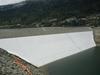
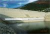
Figure 4 shows the completed installation in May 2005 with a rapidly rising reservoir. Waterproofing work was completed in mid May 2005 on schedule despite significant weather delays. The reservoir completely filled to el 1206m on 7 July 2005 and the seepage readings were 400 l/sec, 47% down from the 2003 results. The goal of the geomembrane system installation was 340 l/sec, or a reduction to 40% of the 850 l/sec limit set by the state dam safety regulators. The geomembrane system achieved a reduction to 400 l/sec, or 47% of limit set by regulators. This reduction provides PG&E a significant margin below the regulatory limit insuring the reservoir can be filled and operated each year without the need to limit reservoir levels insuring maximum power generation.
Financial results
The Salt Springs Geomembrane project was a fixed price contract issued by PG&E to Carpi USA for the geomembrane installation with time and material clauses for surface preparation and weather costs. The surface preparation costs were projected at the beginning of the contract, but the final charges were based on recording the actual materials and labour related to surface preparation. PG&E had a full-time inspector on site that monitored the geomembrane installation and the areas for surface preparation to insure they were appropriate. One of the big advantages of using the geomembrane system is that it can accommodate the rough subgrade by using base layers (thick geotextile and added protective geocomposite). The surface preparation was limited mainly to patch the lower portion of craters in the face, but not making the surface smooth. Originally, the anticipated surface preparation costs were based on the area of el 1155m to 1206m, upper portion of the face of the dam. Once the installation area was relocated to lower down the face in area 1146m to 1192m, all involved recognised the surface preparation costs would increase, but, because the area was underwater, no estimate was given. The final costs show the geomembrane installation was performed on budget with the surface preparations costs increasing because of the rough dam face in the area 1146m to 1155m.
The final price for the geomembrane installation and surface preparation was completed within 2% of budget. The per square meter cost for the geomembrane installation increased due to the more difficult access further down the face. However, the reduced area of installation over the more challenging lower face of the dam kept the overall cost near the original budget. Thus, the change in the middle of the project for the area of installation enabled PG&E to maximise the seepage reduction without changing the overall budget.
Author Info:
The authors are: Erick Larson and Ray Kelly, Pacific Gas & Electric Co, Trent Dreese, Gannett Fleming, and John Wilkes, Carpi USA
TablesSequence of Events