A stable environment
14 July 2005MAI Self Drilling Anchors have been used at the Tala Hydro project for stabilisation of the desilting chamber walls and for tunnelling in poor rock mass conditions on the headrace tunnel
THE Tala hydroelectric project is located in Chukha Dzongkhag in western Bhutan. The five comparatively remote sites that constitute the project are accessed from India through the border crossing at Phuentsholing, and thence towards the Bhutan capital Thimphu along the winding, steep, predominantly single-width National Highway No 2. The dam site is about 85km by road from Phuentsholing, and is located near the village of Wangkha, on the Wangchu river, some 3km downstream of the tailrace outfall of the existing 336MW Chukha hydro station.
The client is Tala Hydroelectric Project Authority (THPA), a body set up specifically to carry the job to a successful conclusion. THPA has split the project into five major components, and awarded these on a competitive tendering basis to three major construction companies of India, namely Jaiprakash Industries Limited, Hindustan Construction Company and Larsen & Toubro Limited. These contracts, designated C-1 to C-5, are closely monitored by THPA so that any changes required can be expedited with minimum delay.
C-1 comprises the dam complex and 6km of the headrace tunnel (HRT); C-2 involves excavation of the HRT from the 6km mark to the 11km mark; C-3 covers HRT excavation to the 15km mark; C-4 covers completion of the HRT to the 22.9km mark; and C-5 comprises the surge shaft, power house and tailrace tunnel.
All were set up with separate access and power supply, so that there is minimum interference between contracts. The power house generating plant has been designed by BHEL with the assistance of Kvaerner, and two alignments for the extra 400kV transmission lines have been optimised.
Main features
The diversion tunnel will provide live storage capacity of 3.2Mm3, between full reservoir level of 1363m asl and minimum drawdown level of 1352m. Sluices located in the middle portion of the dam are designed for a flood discharge of 10,600m3/sec through five bays equipped with 6.5m x 13.15m radial gates, with a provision of a sixth 4m x 3m bay for removal of logs. The three power intakes located on the right bank of the reservoir will enable diversion of a discharge of 171m3/sec. Three desilting chambers sized at 250m x 13.9m x 18.5m will allow the incoming water to settle sufficiently to remove silt particles of up to 0.2mm. A flushing tunnel will remove the sediment, and carry it back to the Wangchu river downstream of the dam. A 22.97km long, 6.8m finished diameter, 50m2 modified horseshoe-shaped, concrete-lined HRT with design discharge of 142.5m3/sec will carry the intake water to the turbines. This utilised five intermediate adits to facilitate its construction. The HRT has been excavated at 7.5m diameter under a minimum rock cover of 60m and maximum of nearly 1km.
A 184m high, 15m diameter underground restricted orifice surge shaft is being provided at the downstream end of the HRT to alleviate any overpressure from the 860m head of water. Two steel-lined pressure shafts inclined at 51º, each 992m long and 4m diameter emanate from the surge shaft and trifurcate into 2.3m diameter penstocks near the power house, to feed the six turbines. Two intermediate adits facilitated construction of the pressure shafts. The underground power house, 206m long by 19m wide and 45.5m high, with six 170MW Pelton turbine-driven generating units with 10% continuous overload capability and spherical main inlet valves, will provide a total capacity of 1122MW.
A 191m long, 16m wide, 27m high transformer cavern will house nineteen 13.8/400kV, 70MVA single-phase transformers and one 63MVAR three-phase Bus Shunt Reactor and 400kV Gas Insulated Switchgear. Two 400kV double circuit transmission lines with a total circuit length of 126km have been installed to reach the border with India. A 400/220kV substation will be constructed for connection with the existing 220kV system. A 3km long x 7.75m diameter tailrace tunnel will discharge the water back into the river.
Progress
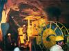
In the tunnels, Atlas Copco Boomer 352s were used in rock classes 1, 2 and 3, where the average advance was 120m/month, and in class 4 rock up to 70m/month. Class 5 rock, which had to be fully ribbed at 60-75cm intervals, strutted, bolted, meshed and shotcreted, slowed advances to 30m/month. Atlas Copco Rock Tools supplied the start-up packs of drilling accessories, and supplied consumables to all three contractors ever since. It also supplied its Terox S5 grinders to ECC and Jaiprakash. The Atlas Copco Secoroc button bits were reported by the contractors to be achieving up to 30% longer life than expected.
The dam site is located in the Thimphu gneiss, and the section of HRT up to 14km downstream from C-1 is in gneiss with quartzite bands and biotite schists. There are joint sets, and the rock is highly faulted, with foliation shears of varying thickness up to 30cm. From 14km to 23km, the rock type is biotite gneiss with bands of quartzite, mica schist, and sericite schist with amphibolite. Rock conditions merit 3 - 4 on the NGI Q system, with pretty poor conditions affecting parts of C2, C-3 and all of C-4. The rock formation in the power house and penstocks, envisaged to be in classification 2 - 3, showed a large variance during actual excavation.
Rock quality was established by an initial survey in which 3 x 230m long exploratory boreholes were drilled along the alignment. A second series of six holes was drilled on the penstock alignment, and a seventh on the centre of the surge shaft. As a general rule, in places where the cover was less than 200m along the alignment, one of a total of 16 cored holes was put down. Coring was also carried out from the access drifts wherever necessary, to fill any gaps in the geologists’ knowledge. Maximum overburden on the scheme is 1200m, and minimum is 65m, with an average of 400-700m.
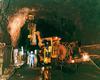
Desilting chamber support
The desilting arrangement at Tala project comprises three underground chambers of 13.9m wide, 18.5m high and 250m long with a continuous hopper formed at the base to efficiently collect suspended silt with particle size of +0.2mm.
The crown portion of the chambers has been supported by rock bolts and steel ribs embedded in concrete or shotcrete, and the walls have been supported by rockbolts and RCC cladding. In Chamber No 3, where rock conditions were very poor, additional support to the right wall has been provided using MAI anchors.
MAI anchors have been successfully used for stabilising the RCC wall of desilting Chamber No 3, behind which enormous cracks had been observed by borehole camera investigation. The strata encountered was so fragmented that the drilled holes would not stay open long enough to install longer rockbolts. The wall of the chamber has been anchored to the deeper competent rock using one row of 114 MAI anchors with 20m length and 38mm diameter at 3m centres, and another row of 36 MAI anchors with 24m length and 51mm diameter at 3m centres.
MAI Anchors in HRT
MAI anchors have been found to be very effective for stabilisation of rock mass in very difficult conditions in the HRT where they have been used for draining the rock mass and for grouting, depending upon the requirement to improve the rock strata.
MAI SDA of 38mm diameter and 8m to 12m long have been used widely in a zone of adverse geological conditions in the HRT between Mirchingchu downstream and Kalikhola upstream diverted alignment. These anchors are used both for drainage purposes, and for anchoring the steel arches and sidewalls.
For drainage purposes, 8-12m long anchors were installed around the periphery of the tunnel wherever seepage of underground water was noticed. These anchors were very effective in channelling the seepage through their hollow core.
For anchoring steel arches, anchors of 8m in length were installed in a systematic pattern. Wherever instrument data indicated a rising trend of load, longer anchors of 12m were installed. Although there was an option of simultaneous drilling, these anchors were first inserted and, if underground water was tapped through any anchor, no grouting was carried out. The anchors with no water seepage were grouted.
Pull out strength
Pull out tests were conducted on 38mm diameter and 20m long MAI anchors installed on the right wall of the desilting chamber, to check the efficacy of grouted anchors in the pull out load of 32t, which was 80% of the yield load specified by the manufacturer. Both MAI anchors passed this test, with displacements of 11mm and 17mm respectively.
Two 38t pull out tests were conducted on 38mm-diameter, 8m-long MAI anchors to check the efficacy of grouted anchors in the poor strata in the HRT. These passed, with displacements of 16mm and 22.8mm.
Load cells were installed on two MAI anchors of 51mm diameter and 24m long in the desilting chamber, and the load was found to be less than 3.5t in both anchors.
Self Drilling Anchors
MAI Self Drilling Anchors (SDA) were in widespread use at Tala for stabilisation of the desilting chamber walls and for tunnelling in poor rock mass conditions on the HRT.
SDA are reinforcement tools which, unlike other types of rockbolts, are equipped with a drillbit of their own which allows them to be installed in one operation in rock, highly fractured weak formations, and even soil where the drill hole collapses and conventional anchor systems cannot be installed.
The SDA system is a concept based on a threaded steel bar which can be drilled in and set without the use of a casing. The bar has a hollow core, which is used for simultaneous flushing or grouting, and its left hand rope thread allows it to be connected to all conventional drilling systems, such as Atlas Copco Rocket Boomers, Boltecs and surface drillrigs.
The advantages of self drilling anchors (SDA) can be summed up as follows: they are particularly suitable for very difficult and unstable ground conditions; re-drilling time due to collapsing boreholes is avoided, and speed of installation is high, with no primary drilling required; the drilling, placing, and grouting of the anchor is performed in one single operation, reducing the drill labour required for cased boreholes; and, since conventional rotary percussion drilling equipment is used, the method of installation is very similar for all ground conditions and in all directions.
SDA rods are manufactured with continuous ISO standard threads, allowing the flexibility to adjust the bolt to the actual requirements at site without any wastage or delay.
Transportation and handling of SDA to and on site is safe and economical, because the commonly used rod length of 3m to 4m of anchors can be extended longer depths depending upon the geology or site requirements.
To summarise: SDA fits Atlas Copco standard Boomers; the self-drilling system eliminates the requirement for a cased borehole; SDA is suitable for working in limited space, height, and in areas of difficult access; it features a simple post grouting system; and SDA can be utilised for drainage of strata.
The system can be installed in a variety of different soils and ground conditions, ranging from sand and gravel to inconsistent fill, boulders, rubble and weathered rock, as well as through footings and base slabs. Underground applications include: radial anchoring for stabilisation of tunnel circumference during excavation; as forepoles, piles or as an umbrella for advance protection of the excavation; as roof piles for reaction load of steel support arches; slope stabilisation of a tunnel portal and soil nailing.
Main components of SDA
• The bar/anchor, with a standard rope thread, which produces an excellent bond between the bar and grout, as well as enabling connection to all Atlas Copco Boomer and surface drillrigs.
• The NG-coupler, which enables direct end-to-end bearing between each rod, reducing energy loss and ensuring maximum percussive energy at the drillbit. It has a thread arrangement in which the top half of the thread is rotated against that of the lower half, providing a centre stop for each bar, All couplers exceed the ultimate strength of the bar by 20%. To enable the correct seating of each bar within the coupler, all bars have a precision cut at right angles to enable end-to-end bearing. A quarter turn back of the coupler on the lower bar will ensure optimum seating of the upper bar within the coupler.
• The hexagonal nut is machined with right-angled edges on both ends and is tempered to meet any stringent specifications and the daily operations of underground works. All nuts exceed the ultimate strength of the bar by 20%.
• The bearing plate is steel, with a centre hole allowing articulation of 7º in all directions.
• The sacrificial drill bit is the most crucial part of the anchor system, and is responsible for the productivity of the installation. These come in a large range, to suit the changing demands of geology encountered on different projects.
MAI anchors are available in lengths of 1m to 5m, with diameter varying from 25mm to 76mm, and internal diameter varying from 14mm to 45mm. The length of the anchors can be increased by coupling different lengths together. It can be cut at any place, due to the continuous thread system. The average yield strength varies from 540MPa to 670Mpa, with tensile strength variation at 690MPa to 880MPa.
Borehole flush
Self drilling anchors are installed with air driven or hydraulic rotary percussion drilling equipment, and using a borehole flush medium suitable for the specific ground conditions.
There are three types of borehole flush: water flush for long boreholes in dense sand, gravel formation or rock conditions, for better transportation of large cuttings and cooling of the drill bit; air flush for short boreholes in soft soil such as chalk and clay, where water spillage is to be avoided; simultaneous drilling and grouting (SDG) for all lengths of boreholes in all unconsolidated soil conditions.
Using SDG, the grout stabilises the borehole during installation, providing a better grout cover along the nail shaft. The grout has good penetration into the surrounding soil, so higher external friction values are reached, and the installation is completed in a single drilling operation, which saves time.
By utilising a sacrificial drill bit, the SDA is drilled continuously forward without extraction, until the design depth is reached. To reach a required nail length of 12m to 15m, 3m to 4m standard rod lengths are easily coupled together.
When using the first two flush types for the drilling operation, the soil/steel interface has to be created by grouting through the hollow stem of the anchor. The grout exits through the flush holes of the drillbit, and backfills the annular space around the nail that has been cut by the larger diameter of the drillbit.
For the third flush type, the flush medium is already a grout mix, which has the ability to harden after the installation process is completed.
Summary
Based on experience with MAI anchors at Tala, the following conclusions are drawn: MAI SDA are useful for anchorage and drainage purposes in very weak rock mass where drillholes cannot stand; cement grouted MAI anchors were able to take 32t pull out load, which is 80% of the yield load specified by the manufacturer; in a reach where adverse geological conditions required forepoling, MAI anchors were used very effectively for releasing pore water pressure behind the forepole umbrella.
Author Info:
Thanks are given to the THPA and its contractors Hindustan Construction, Jaiprakash Industries, and ECC Group for their inputs to this article.
For further information, contact Atlas Copco Rock Drills AB, SE-701 91 Örebro, Sweden. www.atlascopco.com/rde
A version of this article first appeared on www.tunnelbuilder.com. Click on the weblink below for further information
| Safer and Faster |
| Stabilisation of the rock mass was undertaken in very poor rock mass conditions at Tala hydroelectric project in Bhutan, where MAI anchors were crucial in stabilisation of the walls of the desilting chambers and as primary support during excavation of the headrace tunnel. The same anchors have also been found to be very useful in reducing pore water pressure behind the support system. |