Behaviour analysis at El Cajon dam
23 August 2007J D Aleman Velasquez and S Villegas Lesso describe the general characteristics of Mexico's El Cajon project and present an analysis of its behaviour during construction and after first filling
The El Cajon hydroelectric project has recently been constructed in the Mexican state of Nayarit. The project is located approximately 80km east of Tepic city, on the Santiago river, 60km upstream of the existing Aguamilpa project.
The project features a 750MW capacity power station equipped with two Francis turbine-generator units supplied by Russian manufacturer Power Machines. The schemes reservoir will help regulate the basin runoff and benefit the Aguamilpa region.
A brief description of the geological conditions and the main structures at site are presented in the first part of this paper, followed by details on the design and behaviour of the dam.
Project description
General geology
The works were localised mainly in an Ignimbrite rock of riodacitic composition, which is differentiated in three units denominated TicU1, TicU2 and TicU3. The rockfill used in the dam mainly came from the unit TicU1, obtained from the rock banks of the right riverbank (Garrido et al, 1995).
The rocky mass of the site where the works are located – particularly on the left riverbank – present a number of geological faults and superficial thickness of decompressed rock with values RQD from 0 to 50% up to 50m deep. This situation implied excavations and treatments to the rock were needed in order to obtain an adequate foundation for the plinth.
Diversion structures
These consist of two 14 x 14 diversion tunnels (734 and 811m long) excavated in rock, located on the left bank. The tunnels are designed to discharge 6481m3/sec, with two main cofferdams. The upstream cofferdam is 48m high, with the downstream cofferdam standing 15m high.
Generation works
The project features an open power intake channel, two penstocks, an underground power house housing two 375MW Francis turbines (maximum capacity of 416.7MW each), a surge chamber, tailrace tunnel and outside switchyard, all located on the right bank.
Spillway
The spillway, also located on the right bank, is of open channel design, controlled by six gates with a total capacity to discharge 14,864m3/sec when conveying the design flood with a peak flow of 15915m3/sec (Tr = 10 000 years).
Geotechnical design
Zoning of the dam
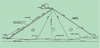
An extensive campaign of field studies and laboratory tests were carried out to determine the geotechnical properties of the rockfill that would be used in the dam. Diverse stress-deformation analysis of the dam using the finite element method (FEM) was also carried out. In accordance with these results, the zoning of the dam and construction specifications shown in figure 2 were proposed.
The seismicity of the region is low, so seismic analysis was not a major consideration during the dam design.
Field and laboratory studies
To study the strength and deformability parameters of the rockfill, a 12.5m high model embankment was built. Here layers of different thickness were placed (40, 60 and 90cm) and the number of compaction passes and the weight of the vibratory roller (7.5t and 10t) varied.
The dry density was reached and the corresponding void ratio of the rockfill was determined.
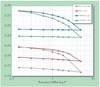
Load and permeability tests were also carried out on the embankment, while triaxials giant tests (in specimens of 30cm of diameter and 70cm of height) and giant oedometric test (in specimens of 110cm of diameter and 100cm of height) were conducted in the laboratory, together with an unconfined compression test on rock cores.
This allowed the index properties for the rockfill to be obtained. The results of these tests are shown in Table 2 and Figure 3.
Behaviour during construction
Construction of the El Cajon dam began in July 2004. Two years later, on 14 July 2006, definitive closing was carried out and the first filling began. In general, the specifications of layer thickness, grain size distribution curves, number of compaction passes, addition of water and rockfill quality were accomplished thanks to strict supervision. This meant the rockfill of the 3B, T and 3C zones reached void ratios of approximately 0.39 (calculated with the classical equation: e = Ss/rrockfill -1) and 0.270 (calculated as: e=??rock / ?rockfill -1, where rrock is the density of the rock, in t/m3; and
rrockfill is the density of the rockfill, in t/m3).
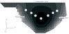
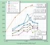
Extensive instrumentation was installed to monitor the displacement of the dam. Hydraulic levels were installed in three sections of the dam (including the maximum section) and at three different elevations. Three-dimensional extensometers were also placed in the perimeter joint plinth-concrete face, while unidirectional extensometers were installed in some tension and compression joints of the concrete slab. Settlements measured at the end of construction can be observed in the maximum section of the dam (Figure 4). The maximum settlement occurs in the material T, with a value of 80cm.
The deformability modulus (E), obtained through measurements of settlement, provided values between 90 and 100 MPa for the material 3B, between 120 and 160 MPa for the T and 70 MPa for the material 3C. These modules are relatively high for a rockfill originating from a rock with a density of 2.37t/m3 (23.3kn/m3 of volumetric weight). This positive behaviour is attributed to the following aspects:
1. A well graduate grain size distribution curve and a good quality rockfill.
2. Abundant addition of water during the construction.
3. Utilisation of a vibratory roller of 12t mass in the drum.
On the other hand, the difference among the modules was from 1.2 to 1.6 times between the materials 3B and T, and almost 2 to 1 between the material T and 3C. This relatively small difference was achieved by using similar grain size distribution curves of the different materials and the utilisation of thickness layers which were not too dissimilar among the diverse zones (80, 100 and 140cm for the zones 3B, T and 3C).
Less deformability in the material T is attributed to its biggest confining stresses. Indeed, the transition zone is the more loaded during construction, but it is also the one that has bigger lateral confining, explaining why the deformability module is between 30 and 60% larger than the material 3B.
Utilising previous information, back analyses were carried out with the finite element method (FEM) using diverse soils models (lineal, hyperbolic, elastic-plastic to simulate the stress-strain behaviour of the rockfill). Figure 5 presents the obtained contours of settlements using a lineal elastic model. It is the authors' opinion that this model reproduces the measured settlements with appropriate accuracy.
During the first filling, with the reservoir to the elevation +380.0 (90% of the total filling), a maximum settlement of 23cm was been measured in the concrete face. The maximum movements measured in the perimeter joint are: 8mm of opening, 23mm of joint offset, and 3.3mm of tangential movement. Figure 6 shows the contours of measured settlements due to the filling.
Again, FEM analyses were carried out to try to reproduce the measured settlements and to investigate the maximum compression stresses in the concrete face. The stress-strain behaviour of the dam was again well simulated with a lineal elastic model, considering Ef = 2Ec,[3] where Ec is the elasticity modulus obtained in the back analysis of the construction and Ef is the elasticity modulus during filling [3]. The contours of settlements and the compression stresses calculated in the concrete slab appear in figures 7 and 8. In these models it was considered that relative displacement didn't exist on the concrete face or the rockfill that supports it.
It was observed that the calculated maximum compression stresses are present in the middle of the concrete slab with a magnitude in the order of 7 MPa – that does not represent a risk of rupture of the concrete slab. The problem of horizontal tension stress was eliminated with the perimeter joint plinth-concrete slab and vertical joints in the slab panels at each 15m. It is necessary to comment that during the design, on both the left and right banks in the upper part of the concrete slab, the separation of the joints decreased to 7.5m in order to absorb the high tension stress that would be presented. A summary of the analyses and measurements is given in Table 3.
Conclusions
Considering results of previous studies, together with direct measurement of the dam behaviour during construction and first filling, we can conclude the following:
1. The detailed study of the index properties and the geotechnical parameters of the rockfill, allow a more rational design of the dam to be carried out. However, the analyses and mathematical simulations performed should consider behaviour of existing dams.
2. It is possible to model the stress-strain behaviour of these types of dams with a simple lineal elastic model.
3. The above mentioned point is valid despite the fact that the elasticity modules increases with the confining stress, as was measured in the material T of the El Cajon dam.
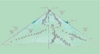
Table 1 Table 2 Table 3 Figure 1: General arrangement of the projec:1. Deviation tunnels; 2. Cofferdam, 3: Dam; 4. Power house; 5. Spillway Figure 1 Figure 2: Zoning of the dam and used compaction specifications Figure 2 Figure 3a: Results of the giant oedometer test - compressibility curve of the rockfill Figure 3a Figure 3b: Results of the giant oedmeter test - variation of the oedometric modulus Figure 3b Figure 4: Contours of settlements measured at the end of construction, in cm (courtesy Subgerencia de Seguridad de estructuras, CFE) Figure 4 Figure 5: Contours of settlements obtained in the back analysis, in cm Figure 5 Figure 6: Contours of the measured settlements in maximum section, cm, due to the filling (courtesy Subgerencia de Seguridad de estructuras, CFE) Figure 6 Figure 7: Contours of calculated settlements due to the initial filling in the maximum section, in cm Figure 7 Figure 8: Contours of horizontal compression stresses in the middle concrete slab plane, due to the initial filling in the maximum section, in MPa Figure 8 Figure 9: Aerial photo of El Cajon dam, January 2006 Figure 9 Figure 10: Aerial photo of El Cajon dam, September 2006 Figure 10 Author Info:
J D Aleman Velasquez and S Villegas Lesson are with the Electricity Federal Commission, Mexico
TablesTable 1 Table 2 Table 3