Challenges in turbine transport
13 August 2008R C Silva, L J Pedroso and A Albuquerque detail the challenges that were met during transportation of a turbine runner to Brazil’s Tucurui dam
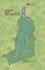
Tucurui dam, located on the Arguaia-Tocantins basin in Brazil (Figure 1), is owned and operated by Brazilian power company Eletronorte, a subsidiary of Centrais Eletricas Brasileiras - Eletrobras.
Construction of the project – which involved the use of 1.08M tons of cement and 222,000 tons of steel – occurred in two phases. The first stage began in 1976 and was completed in 1984, with twelve Francis turbines installed in the power plant, representing 4125MW of the full anticipated installed power of 8370MW.
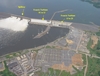
The second stage of construction began in 1998 and was completed in 2006. Upon completion of this stage a further 4245MW capacity was added, through installation of another 11 turbines (Figure 2).
This paper details the logistical issues encountered during delivery of one of the turbine runners, together with technical information on the turbine installation. It is pointed out that the methods and means of transport detailed here were utilised during transport and installation of the 11 turbines that formed part of the second stage of construction.
Characteristics of the turbine runner
The turbine runner is made of cast steel designated ASTM A 743–CA 6NM. The runner is 5m high with an outlet diameter of 8.3m. The Francis turbines used at the plant are designed with a capacity of 382MW and a nominal inflow of 682m3/sec.
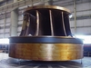
In general, turbine runners are composed of three distinct parts: a crown and a band made of cast steel that weigh around 107 and 51 tons respectively, and 12 curved blades made of calendering plates. Part of the blade surface is coated with 5mm thick stainless steel to protect from cavitation. Each of the blades weigh 5.7 tons and have an average thickness of approximately 130mm.
In the central part of the runner, there is also a steel runner cone that weighs 1.2 tons, designed to assure continuity of the hydraulic flow. Figure 3 shows the turbine runner.
Power station
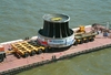
During construction of the two power stations which form the Tucurui project, turbines where placed in wells. These wells were covered by a steel cylinder designed to help in the well concreting and to function as a support to inferior closing of the generator. The wells are 10.5m in diameter with a depth of 5m.
Turbine runner transportation
General considerations
An efficient transportation support is fundamental for good logistic performance and supply management, as delays in equipment delivery can have a fundamental effect on project completion.
The most common problems faced during transportation of material are poorly conserved roads and the lack of control and regulation laws for transportation in Brazil. Most of Eletronorte’s business is concentrated in northern Brazil which still has a considerable lack of adequate infrastructure, meaning the transport of exceptional loads, such as the turbine runner, can be a great challenge.
From the first stage of construction, solely road transport of heavy equipment from industry to the dam was not recommended. This was due to the length of transportation (over two months), high costs, and the inability of existing roads in the north to handle large loads.
As a result, Transport Assistance of Eletronorte (AST) carried out a viability study on the condition of Brazilian roads between industry and the dam site, taking into account particular characteristics of weight and dimensions of the charge and also the limitations of certain roads.
Based on this report, Eletronorte decided to transport large equipment manufactured in Brazil – such as the turbine runners – using a combination of roads, sea and rivers. Equipment left industry by road to be transported to a nearby port, where they were transferred by ship to Bele?m Port, with the final part of the journey being by raft to the project site.
Transport of the turbine runner
A description of the passage of turbine runners to Tucurui dam is described below, with transportation time being over one month.
The runner was manufactured in Taubate city in Sao Paulo. Once complete it was carried to Santos Port on a wagon, which measured 93m long, 9m wide with 296 wheels, including the trucks that pulled it. The set weighed 640 tons, including runner, wagon, trucks and articulated beam/gondola. The load allowed for each wheel is about 5 tons. The load was driven a distance of 210km, with the itinerary and parking places planned th Company of Engineering of Traffic (CET).
As part of the route, 45km was covered in Sao Paulo city with an average speed of 5km/h. The wagon was authorized to pass through the city at night between the hours of 11:00pm to 6:00am to avoid disturbing traffic. The rest of the time it was parked in designated places. It took ten days to pass through the city.
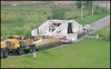
Some of the problems encountered during transportation included the fact that CET had to raise a concrete footbridge by two cranes, because the turbine runner was higher than the bridge. It was also necessary to remove light poles, disconnect electrical and telephonic systems and remove fencings, traffic lights, etc.
When it arrived in Santos Port, the transportation set shown in figures 5 was discarded and the runner was transferred to a wagon road using a crane.
The new transport had the following characteristics: twelve axles in transversal direction; three lines (longitudinal direction) with four wheels, each one totalizing 144 wheels; a truck which has 700HP and traction capacity of 500 tons; and an auxiliary truck with 298HP and 100tons of traction capacity. Runner and set transportation embarked on a ship type roll on-roll off to Belem Port and travelled a distance of 4600km. Figure 6 shows the road wagon detail.
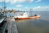
Upon arrival at Belem Port (Figure 7), the road wagon and the turbine runner disembarked the ‘Starman America’ ship and the set was driven to Dock Company of Para. The road wagon once again passed through urban areas to arrive at Belem fluvial terminal (Figure 8).
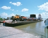
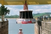
In Bele?m, the truck/wagon and turbine rotor were loaded onto a raft for its journey to Tucurui Port. This transport had a capacity to carry 1000 tons in capacity; 16m in width; 50m in length and a pusher of 1000 tons of weight. The wagon was anchored to the raft at eight points with steel cables to avoid set sliding. Figure8 shows a view of the raft/wagon and rotor.
The raft sailed 330km over ten days along the Tocantins River to arrive at Tucurui Port. Along the river, rafts require a maximum draft of 1.5m and adequate dimensions to guarantee the stability when loaded or not. Deck structure was strengthened to carry nearly 350 tons.
Once it reached Tucurui Port, the runner turbine was lifted by an overhead travelling crane (250/25tf) using four steel cables and placed on the new transportation set to be driven to Tucurui power station. Elevation mechanism was fixed in the runner crown as shown in Figure 9, and after that it was elevated to a height of 18.4m.
The runner was transported along the road for 5km, with a metallic frame protecting the equipment. This frame was welded onto the wagon structure, with wood wedges used to absorb impacts during the route.
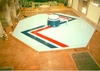
Upon arrival at the power station, the wagon was parked under the rolling bridge 550/60tf inside the power station and runner was lifted and placed on the floor for assembly and installation.
The runner turbine travelled for approximately 45 days, and during the route no incidents were reported. As a result, the transportation plan was repeated for the generators, the rest of the turbine runners, and other large equipment. According to the logistic department of Eletronorte, this transportation plan can be considered safe because it maintains equipment integrity and is low cost compared to other alternatives.
Silva, R.C., Research Assistant, University of Brasilia Department of Civil Engineering (ritasilva@unb.br) Pedroso, L.J., Associate Professor, University of Brasi?lia Department of Civil Engineering (lineu@unb.br) Albuquerque, A., Civil Engineer, Eletronorte Power (antonival@eln.gov.br)
The authors wish to acknowledge Eletronorte for supplying the photos and technical information used in this article