Change of speed - variable units investigated
16 March 2005Variable speed units for pumped storage power plants are becoming a state-of-the-art technology for optimised efficiency in turbine mode and a wide range of power control in the pump mode. K Scherer reports on aspects and challenges for the design of the motor-generators, using Goldisthal pumped storage plant in Germany as an example
PUMPED storage power plants are an essential part of complex electric grids because they provide high additional capacity at an extremely short start up time. Stability of grids becomes more and more a challenge due to higher utilisation of installed capacities for power generation but also due to an increasing number of wind power plants. For quite some time pumped storage power plants were mainly erected in mountainous regions, where natural inflow was used to a large extent in addition to pumping water. To meet future requirements, however, pumped storage power plants are also necessary in areas where a high head design cannot be applied for topographical reasons. In such pumped storage power plants the nominal head is typically in the range of 200m to 400m only, whereas the typical range for rated output is 200 to 350MW per unit. Francis pump turbines and bi-directional motor-generators are more or less a standard for such types of power plants.
Pumped storage power plants as described above are usually characterised by high variations of the actual hydraulic head, which lead to sub-optimal unit efficiencies in turbine operation and varying power consumption in pump mode. Furthermore, due to certain restrictions in the hydraulic design, the utilisation of the available head in the reservoir is limited. In the past, dual-speed units were developed to overcome this disadvantage, using a special arrangement of the stator winding of the motor-generator to shift between two numbers of poles, therefore changing the synchronous speed. This solution, of course, is not very flexible and its application is limited to certain numerical proportions of the two synchronous speeds.
A new technology for pumped power schemes in the medium head range is the use of variable speed units, in which the operating speed can be varied in a certain range of the nominal ‘synchronous speed’. Such a variable speed is made possible by using double-fed motor-generators which are basically operating as asynchronous units by feeding low frequency alternating current into excitation winding instead of DC current.
Key advantages of this technology are: more flexibility in operation; higher efficiency in a wide range of part load turbine operation; a wide range of controllable and optimised power consumption in pump operation; additional and faster features for grid control (shifting the actual speed in addition to conventional control of active and reactive power and frequency); better utilisation of the reservoir because higher variations of the water level can be allowed, therefore optimisation of civil work; additional contribution to grid stability because of high moment of inertia of rotating masses.
Design differences
Basic design concept of synchronous generators
Since units of higher output are normally ‘tailor-made’, the actual design depends on actual requirements and contract specifications, design tradition and experience of the manufacturer and it is the result of an ongoing optimisation process. However, the basic design concept of conventional synchronous generators of medium and larger size has not changed for decades. Usually the stator winding is a three phase winding, embedded in a laminated stator core. The magnetic field is then generated by salient poles which are fixed to the rotor using different concepts. Usually dove-tail designs or T-heads are used to optimise the mechanical system with regard to mechanical stresses during normal operation as well as during runaway-speed, which is the worst case and creates maximum stress levels in the rotating system. These poles consist of laminated sheets in between two solid pole end plates each (thoroughly pressed by bolts) and pole coils which are fixed to the pole bodies. Electrically, all coils of a rotor are connected in series and fed by direct current. The source of necessary excitation energy is either a rotating AC exciter machine with rotating rectifiers or a static excitation unit which feeds the pole coils via slip rings.
It is quite obvious that in case of bi-directional operation additional care has to be taken for designing thrust and guide bearings and the ventilation system. Axial fans, for example, cannot be used in such an operation mode.
The operating synchronous speed itself is the result of an optimisation process on the turbine side and is one of the key input parameters given to the generator design engineer.

nsyn – synchronous speed (rpm)
f1 – grid frequency
p – number of pole pairs
Basic design concept of a double-fed asynchronous generator
Whereas the stator and also the overall mechanical concept of an asynchronous generator are basically very similar to a conventional synchronous one, the entire design of the rotor is completely different.
Instead of salient poles fixed to a solid rotor body or stacked rim the rotor consists of a cylindrical laminated body made of dynamo steel sheets in which a three phase winding is embedded in slots – very similar to the way stator windings normally are embedded in slots of a stator core. By feeding this winding with three phase alternating current of variable frequency the resulting speed of the unit can vary from values below to above synchronous speed.

nact – actual speed (rpm)
f1 – grid frequency
f2 – frequency of the rotor circuit (converter output)
p – number of pole pairs
The source of this AC current is normally a cycloconverter with special advanced control features. Since the range of speed variation has a significant impact on design and costs of the pump turbine, the converter and the generator as well, intensive optimisation efforts are necessary on the entire system.
Key challenges in design of large asynchronous generators
The effect of variable speed operation and related optimisation processes is well described for the pump turbine and the control technology. As mentioned above, for the motor-generator the major difference lies in the rotor – from the designer's point of view. Besides the issues of the electrical layout and mechanical design quite a lot of investigations have to be made regarding the variable speed unit as a part of the electric system in its steady-state and dynamic operational behaviour. The capability of operating in unbalanced load conditions, for example, is a well known part of the design process for conventional salient pole generators with a damper winding. However, basic investigations must be made and calculation methods need to be developed for large double-fed asynchronous generators.
In an overview the following details may be mentioned as special challenges in designing variable speed generators and defining their operational parameters as compared to conventional synchronous generators with salient poles: unbalanced load; single phase sudden short circuit; slip rings and rotor leads; rotor winding; retaining rings; ventilation system; bearings; and shaft line analysis.
Technical issues
iec 60034 claims that generators can be operated with 10% unbalanced load. Conventional generators with salient poles are designed with a damper winding, which is capable of carrying the inverse sequence current in case of unbalanced load. The frequency of the inverse sequence current in the damper winding is twice the frequency of the grid. Due to additional losses and the temperature rise of the generator unbalanced load is limited.
A variable speed motor-generator cannot be equipped with a damper winding because of the three phase power supply to the rotor winding. Hence the three phase rotor winding and the cycloconverter have to carry the inverse sequence current. The frequency of the inverse sequence current in the rotor winding varies with the speed of the rotor.
Extensive simulations have not only shown that variable speed motor-generators can be operated with unsymmetrical loads but have also provided additional information for the design of rotor windings and protection systems. Due to the higher frequencies in the rotor current additional losses will occur in the rotor winding, in the core and in the converter. On the other hand, these additional frequencies can be used by sophisticated protection systems to detect unbalanced load conditions.
Slip rings and rotor leads
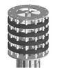
Normally, slip rings are designed for DC rotor currents up to approximately 1000 A and rotor voltages of a few hundred volts. In the case of variable speed double-fed asynchronous generators a set of slip rings for three-phase power supply to the rotor winding must be provided.
A design example is given in Figure 1, which shows a slip ring for rated current of 9000A and a nominal voltage of 4kV.
High load and the very specific environment in the presence of carbon dust require special consideration of proper ventilation and sufficient clearances.
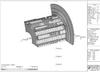
Rotor leads for three-phase AC current ask for special attention because of eddy currents and stray losses. Slightest non-symmetrical heating of the shaft due to eddy currents would eventually create distortions in the shaft and create severe problems with vibrations. Figure 2 shows a result of a detailed analysis using Finite Element calculations.
Rotor winding and retaining rings
The rotor winding is designed very similarly to a conventional stator winding, meaning it consists of a two-layer bar-type winding. The bars are designed as transposed Roebel bars to minimise copper losses and insulated according to a specified test voltage which has a reference to the stand-still voltage in the rotor winding.
Compared to a normal high voltage winding in the stator a major challenge is the winding overhang which must be designed in such a way, that: Required clearances and lengths of potential grading layers can be maintained; Centrifugal forces at maximum run-away speed can be withstood; Proper ventilation is ensured.
New manufacturing methods, special devices and modified test procedures are required to achieve all targets simultaneously.
An innovative solution to support the entire overhang of the rotor winding is the use of non-magnetic forged retaining rings – a design feature well-known for high-speed turbo generators but new as an application for hydro generators. The supporting system consists of shrunk-on outer retaining rings, inner support rings and a special design of spacers in between the winding bars. This lavish system enables necessary support, proper cooling and protection of the high voltage insulation against mechanical damage. It also minimises relative movements between laminated rotor body and the rotor winding. One of the most critical tasks is the forging and machining process of the rings because of the material specification and actual dimensions combined with high requirements regarding accuracy.
Shaft line analysis
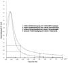
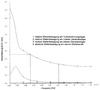
Analysis of the entire rotating system is a standard part in the design process of larger units but requires special attention in case of huge masses and dimensions. In addition to these ‘normal’ tasks a double-fed asynchronous generator provides special features because of the air gap which is considerably smaller than in a synchronous generator. Such small air gaps, however, result in much higher magnetic forces in case of non-symmetric conditions or electric failures in the rotor circuit. Figures 5a and 5b show some results of an entire set of calculations.
Motor-generators for Goldisthal
The pumped storage plant Goldisthal in Thuringia, Germany is well described and presented in a number of papers [4]. Now owned and operated by Vattenfall Europe Generation, it represents one of the most powerful and advanced pumped storage plants worldwide. Detailed investigations evaluated the advantages of variable speed units versus the risks of using such a comparably new technology and of course all short and long term economic implications. Finally, the decision was made to combine conventional pump storage technology (represented by two synchronous mono-speed units) with advanced variable-speed technology (represented by two variable speed units).
For the hydraulic part the contract was awarded to a consortium of va-tech Escher Wyss, voith-siemens Hydro and CKD Blansko Engineering. For the electric part (i.e. motor-generators and converter) a consortium of alstom Energietechnik, VA Tech Elin (now VA Tech Hydro) and VEM Sachsenwerk Dresden was the supplier. The entire responsibility for development, design, manufacturing, erection and commissioning of all four motor-generators was with VA Tech Hydro.
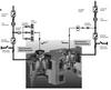
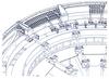
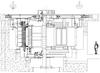
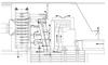
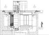
As a part of the optimisation process of the hydraulic system one synchronous unit and one variable speed unit are fed by a common penstock each. Figure 6 is a very simplified basic diagram which shows the electric system for feeding the rotor windings. Figures 7a and 7b are sectional views of the motor-generators to indicate the key differences in design and size. The impressive arrangement for the slip rings in the variable speed unit (Figure 7a) and the shorter dimensions of the stator core of the synchronous unit (Figure 7b) can clearly be seen.
Most of the work for development and basic design including theoretical investigations and simulations for the motor-generators was performed at VA Tech Hydro’s generator departments. Due to the complexity of the design work close interaction and co-ordination with consortium partners were necessary and regular design reviews were held. Additionally, a very successful cooperation with the Technical Universities in Graz, Austria, and Dresden, Germany, took place in some specific areas.
On-site erection work for the motor-generators at Goldisthal started in late 2001, by June 2004 the last of the four units was successfully commissioned and handed over for commercial operation.
Conclusion
Providing peak power in large and complex electrical grids becomes more and more important along with highly advanced grid control strategies. It is quite a complex task and even a challenge to modern grid management to keep such systems in stable and safe operation at minimised costs. Variable speed technology for pumped storage power plants gives new opportunities regarding grid control, efficiency, stability and optimised utilisation of new or existing reservoirs.
Variation of power consumption in a wide range during pump operation can now be combined with significantly improved turbine efficiencies in part load conditions and new possibilities for grid control. By shifting the operational speed in very short time an additional kind of dynamic intervention to conventional control mechanism is available for frequency, active and reactive power.
This technology – installed in Goldisthal pumped storage power plant L in Germany – has already proven its capabilities by fulfilling or even exceeding all specified requirements.
Author Info:
Dipl. Ing. Karl Scherer, VA Tech Hydro Gmbh & Co., Bereich Hydrogeneratoren, Elingasse 3, A-8160 Weiz, Austria. Email: karl.scherer@vatech-hydro.at
This paper was presented at the 13th International Seminar on Hydropower Plants. Contact Dr Eduard Doujak, email: edoujak@pop.tuwien.ac.at
TablesTable 1