Extension project - construction of the 70MW Feldsee scheme
19 January 2007G Berger and K Nackler present details on the design, environmental approval and construction of the 70MW Feldsee pumped storage plant
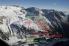
The Fragant group of power plants, located in the Möll Valley in Upper Carinthia, Austria, are owned and operated by Austrian utility Kelag. The plants have an installed output of 334MW and annual generation of 550MkWh, with the Innerfragant power plant storing a further 100MW. Construction of the plants began in 1964, with work completed in 1984 with commissioning of the Wölla power plant. The most significant plants in the group are the high level Zirknitz plant, the main level Innerfragant power plant with the Wurten and Oschenik power plants, plus the low level Ausserfragant plant.
Two reservoirs, Wurtenalm and Feldsee, are part of the power plant group and have been in existence for over 30 years. The Feldsee currently serves as a distant storage reservoir for the Hochwurten-Grosssee reservoir system, with the stored water pumped into the reservoir system by means of several small pumping stations. Kelag is now planning to extend the Fragant group by developing the Feldsee pumped storage hydro power plant using the existing Wurtenalm and Feldsee reservoirs.
Project description
The projected new Feldsee power plant uses the existing Feldsee (upstream) and Wurtenalm (downstream) reservoirs, which will be connected by a penstock approximately 2200m long. A power house with corresponding pump turbine will be situated at the end of a 1820m long upstream penstock, with the tailwater reaching the Wurtenalm reservoir by way of a pipeline approximately 380m long. The same penstock will be used in the opposite direction in pumping mode. A 110kV overhead power line approximately 1800m long will be constructed to deliver energy from the planned power plant to the existing Innerfragant substation.
Reservoirs
The Feldsee reservoir, with an effective capacity of 1.65Mm3, is currently managed as an annual reservoir. The effective inflow to the Feldsee is approximately 3.2Mm3 in a normal year (mainly in the months between May and August). The stored water is pumped to the Grosssee-Wurten system by means of the Gastrog, Stübele and Weisssee pumping stations in order to be utilised by the Zirknitz power plant. The water utilised in the Zirknitz power plant reaches the Wurtenalm reservoir by way of a free-surface flow gallery.
A structure for water removal, which will be assigned the function of an intake or outfall structure depending on the operating mode, will be erected in both reservoirs. Both intakes are arranged below the respective draw-down level and are provided with fine screens. A shut-off unit capable of acting as an emergency shut-off will also be installed.
Penstock
High pressure side
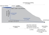
Before final planning of the link between the Feldsee and the power house was carried out, a comprehensive study was undertaken looking at all the parameters – such as geology, pressure surge, minimisation of fall, material costs, etc – which could have an impact on the project. At the same time, various alignments, such as pipe penstock above ground, inclined shaft or vertical shaft version, were investigated. This led to the development of the following design plans.
The intake/outfall structure at the lowest point of the Feldsee will be designed as an intake tower with a four-sided penstock screen. In the transition between the intake structure and the vertical shaft is situated a shut-off unit capable of acting as an emergency shut-off. A water-tight access duct approximately 100m long which has adapted to the terrain leads to this unit. A ventilation pipe for the vertical shaft will also be laid underneath the shut-off unit parallel to this access duct. Starting from the Feldsee intake structure, a vertical shaft approximately 450m deep will be built using the raiseboring method. In this case a 30cm wide pilot bore will be driven from the top to the lowest point – widening to a diameter of 3.7m will take place subsequently by means of a drill head from the bottom upwards. This vertical shaft will be concrete lined with the help of a slip-form construction at an internal diameter of 3.2m, with the bond between the rock wall and the concrete lining injection grouted. Between the low point of the vertical shaft and the power house, a 10m2 gallery with 8% inclination will be fabricated in the conventional way with the use of blast advance, starting from the power house. The final development of this gallery will be lined in sections using different types of lining. Starting from the low point of the vertical shaft, a concrete ring with an internal diameter of 3m will be constructed over a length of 600m by the use of a formwork transport wagon – a geological disturbance zone is forecast for a smaller section, and special lining measures have to be included in the calculations at this point depending on the severity of the disturbance. Injection grouting will also be carried out here between the concrete and the rock. The next 570m of length will be executed with a glass fibre-reinforced unsaturated polyester jointed pipe with internal diameter of 3m or 2.8m and a 12cm thick inner concrete shell. The space between the glass fibre-reinforced unsaturated polyester pipe and the rock wall will be backfilled after concrete is laid through pipe unions. The coaxial gap between the pipe and the concrete and the gap between the concrete and the rock will be pre-stressed by means of grouting. A steel armour with internal concrete ring and a diameter of 2.8m will be installed in the next 139m long gallery section instead of the glass fibre-reinforced unsaturated polyester pipe, but using the same method of construction. In the last 61m long gallery section ahead of the power house a steel armour with multiple graduations of the internal diameter from 2.8m to 1.1m including concrete backfilling and grouting will be constructed. In this area there is conservation instead of an internal concrete lining.
Construction of the Wurten access gallery is necessary to allow construction of the power house and the gallery lining, together with the accompanying grouting and conservation work to take place during the same period. It is also necessary during operation of the power plant to allow access to the penstock for maintenance and inspection work.
Low-pressure side
A gallery, to be excavated conventionally (full section around 13m2) will run from the intake and outfall structure of the Wurten reservoir to a sluice shaft which is fitted with a roller sluice gate to enable the tailrace pipe of the power house to be isolated from the Wurten reservoir.
Adjoining the sluice shaft is a gallery created by conventional driving, into which is drawn a glass fibre-reinforced pipe with a diameter of 2800mm, This pipe will be backfilled with concrete on completion. The total length of the tailrace tunnel is approximately 225m. For the last 155m up to the power house, the pipe penstock route is laid in a trench following the terrain, subsequently sheathed with concrete and backfilled with excavated material. The total length of the tailrace pipe is therefore approximately 380m.
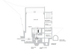
Power house
The topography of the existing narrow valley section determined the location of the power house, and Kelag had to take into account access roads, connection to the penstock and routeing of the flood water/deep sluice channel. The power house will thus be located on the orographic left-hand flank of the Wurtenbach valley at a distance of approximately 320m (leaving the valley) from the fill crest of the Wurten dam. The structure will occupy an area of around 450m2 and will take up an enclosed space of approximately 13,500m3 at a height of around 30m. It consists essentially of six storeys. The entrance level (simultaneously the level of the apron) is set at an elevation of 1623m asl.
Mechanical and electrical equipment
Operation of the hydro power generating set will be fully automated, and remotely controlled and monitored. Start-up of the pump turbine in turbine mode takes place in the water-filled condition. In this case the downstream shut-off valve and the upstream globe valve are opened and the control device is brought into the start-up position. Adjustment of the control device is effected by means of a synchronising unit. The generator output is adjusted via the orifice of the control device once synchronisation to the grid is complete. Start-up in pump mode or in motor mode is envisaged with emptied spiral casing of the pump turbine and by supplying electricity to the motor generator by way of a frequency converter set. The pump turbine is emptied by blowing in compressed air (blow-out unit). Following the start-up and synchronisation procedure and prior to transition to pump mode, the compressed air blown in beforehand escapes through air valves attached specifically for this purpose. A globe valve ND 1,110 on the high-pressure side and an eccentric shut-off valve ND 1,800 on the low-pressure side capable of acting as emergency shut-off units are provided within the power house. The globe valve and shut-off valve are each provided with an appropriate disassembly pipe to allow for dismantling.
Pump turbine
A vertical, single-stage, single-flow, reversible Francis pump turbine is provided as the turbine and pump respectively. The pump concerned is designed to meet the operating requirements with a spiral casing and control device which may be operated at high efficiency both in pump mode and also in turbine mode. The rotor blade speed is 1000rpm in both turbine and pump mode. The characteristic operating data of the planned hydraulic turbine-generator, the maximum output of which is restricted to 72MW, is shown in Table 2. Motor generator
The three-phase synchronous motor-generator with vertical shaft is driven by the flange-mounted Francis pump turbine by way of an intermediate shaft (in turbine mode) or drives the pump turbine (in pump mode).
The rated data is as follows:
•Rated apparent power: 75,000kVA
•Rated power factor: 0.9
•Rated voltage: 10,500V
•Voltage limits: ± 10%
•Rated frequency: 50Hz
•Rated speed: 1000rpm
The generator is designed with an overhead axial non-locating and locating bearing which absorbs the pump turbine's axial forces, and a bottom locating bearing. The radial forces are transmitted to the structure by the top and bottom bearing arm star. Cooling of the closed stator air-cooling circuit is done by air/water-heat exchangers, which are housed directly in the generator annulus distributed around the circumference on the outside of the stator core assembly. Cooling of the bearings is carried out by the use of oil/water heat exchangers.
The rotor of the motor generator with the sliprings, the axial fans and the poles with damper winding and pole connections is designed such that it can withstand the overspeed test without damage at
nS=1,2 xnD. The motor generator is equipped with a static shunt excitation. A start-up converter is required to start up the turbine generator set in pump mode. Underfrequency run-up of the motor generator takes place in the blown-out condition of the pump turbine by way of the frequency converter in motor mode whilst the converter voltage is switched to the isolated motor generator terminals by the grid coupling transformer. The start-up converter shuts down until the next start-up after synchronisation to the grid on the 10kV busbar.
All relevant processes are monitored with appropriate metering probes. In part the monitoring system is of redundant construction. All transmitter values are transferred to the turbine generator's instrumentation and control system (the mechanical protection) which isolates the turbine generator set from the grid in the event of a malfunction and shuts it down.
10kV switchgear and power take-off
Power take-off from the motor generator to the 10kV switchgear is by means of a short-circuit-proof, air-insulated busbar system. The busbars are designed as a single or twin busbar system depending on the current intensity. The 10kV switchgear is made up of nine modular, air-insulated, short-circuit-resistant, metal-encapsulated single panels. The switchgear cells are fitted with all the transformers required for measuring, protection and synchronisation.
Grid coupling transformer, 110kV switchgear
A three-phase oil power transformer with oil expansion tank will be set up in the transformer room to match the 110kV mains voltage to the generator voltage. The transformer is designed to be thermally and dynamically resistant to short-circuiting in all parts and is constructed for oil self-cooling. The output of the generator transformer is 75MVA.
The 110kV switchgear is designed as a SF6-gas-insulated, metal-encapsulated high-voltage switchgear system. Spatially the 110kV switchgear is located on the 2nd floor directly above the grid coupling transformer. The panel width is between 1000 and 1200mm depending on the manufacturer. Transition from the encapsulated switchgear system to the connection point of the 110kV overhead power line is created by means of an outdoor SF6 bushing.
Station-service system
The main incoming supply of the 400V station-service busbar is from the 10.5kV busbar by way of the 10.5/0.4kV station-service transformer, which is is housed in its own transformer room on the 2nd floor of the basement. Secondary supply of the station-service busbar is from the 20kV mains, which together with a 20kV switchgear cell and a mains transformer, is situated in a room on the 2nd floor of the basement. The 20kV switchgear consists of a load disconnector and an earthing disconnector. Automatic switchover to the station-service supply of the 20kV mains station is carried out if there is a failure of the station-service incoming supply from the power plant's station-service transformer. The 20kV network may be supplied by way of an auxiliary turbine generator set with a low-voltage generator which is situated in the Innerfragant power plant.
Operation
Operation of the Feldsee pumped storage hydro power plant will, like the existing power plants of the Fragant group and all Kelag power plants, be completely automated, remotely controlled and remotely monitored by the energy control centre in Klagenfurt which is manned 24 hours a day. In this case set points for active-power and reactive power output are prescribed for the generator-related controllers and are converted by them into corresponding actual values and monitored for any system deviations. All relevant processes will be monitored with the appropriate measuring probes, sensors and transmitters.
All transmitter values are transferred to the turbine generator's instrumentation and control system (the mechanical protection) which isolates the turbine generator set from the grid in the event of malfunction and shuts it down.
In line with the operating philosophy and the existing operating opportunities for the present turbine generator sets in the Fragant group of power plants, there is also a facility for operating the Feldsee power plant's turbine generator set locally in 'automatic mode'as well as in 'manual interlocked mode' and 'manual mode'. Appropriate telecommunications devices and expansions will be provided in the Feldsee power plant and in the energy control centre in Klagenfurt for remote control, remote monitoring and integration into Kelag's digital transmission network.
Kelag grid/110kV overhead line
The Feldsee pumped storage plant will be connected to the already existing 110kV grid support structure of the Innerfragant transformer substation through a 110kV overhead line. The grid connection with a line length of 1.8km is located in the village of Flattach in the Innerfragant region. The planned route of the overhead line takes into account both the existing structures and the prevailing geophysical conditions. The project includes construction of a 110kV overhead line from the Feldsee plant up to the Innerfragant substation, integration of the 110kV overhead line into Feldsee and integration of the 110kV overhead line into the existing Innerfragant substation
Licensing procedure
An Environmental Impact Assessment (EIA) procedure is compulsory for power plant projects with an output over 15MW in Austria. The EIA procedure is a concentrated procedure with the inclusion of all legal materials with which a single authority authorises the entire licensing procedure in a single official notification. With this method, there is a certain guarantee that the licensing procedure will be utilised within a limited period of time.
Kelag made the decision at the end of 2004 to initiate the licensing steps for the Feldsee project and presented the project to the public for the first time. At the beginning of 2005 an organisation was set up to deal specifically with the EIA. The Environmental Impact Assessment Declaration (EID) was issued in a very short time – along with the detailed technical planning – and it contains the following three main sections:
•Licence application with detailed explanation of all legally relevant reference levels.
•Environmental Impact Assessment Declaration with a total of 15 extensive specialist reports and a detailed summary.
•Technical submission, consisting of detailed technical reports and enclosures of plans, divided in each case according to structural works and technical power plant equipment.
Subsequently the EIA was carried out by the authority and positive EIA notification was issued in the middle of June 2006.
Parallel to the EIA procedure, at the end of 2005 Kelag had already started calling for tenders for deadline-critical supplies and construction services. Thus it was possible to award contracts for the most important construction sections and the mechanical/electrical equipment immediately after the EIA notification became legally effective.
Commencement of construction, with creation of the necessary infrastructure, started at the end of July 2006. Construction began on the main construction section for the horizontal gallery in November 2006. Commissioning of the pumped storage hydroelectric plant is planned for 1 December 2008.
Author Info:
Prok. Dipl. Ing Gerald Berger and Prok. Dipl. Ing. Karl Nackler, Kelag - Karntner. Email: gerald.berger@kelag.at, karl.nackler@kelag.at.
This paper is based on a presentation at the 14th International Seminar on Hydropower Plants, held from 22-24 November 2006. For further information on this event, contact Dr Eduard Doujak, email: edoujak@pop.tuwien.ac.at.
TablesTable 1 Table 2