Focus on Sauda
19 April 2006The largest hydro powernstruction in Norway is Sauda reconstruction and enlargement scheme, which is set to increase the energy production from the Sauda catchment by approximately 500GWh/yr. Extensive underground work is a large part of the project, as Øyvind Engelstad reports
Private power company Aktieselskabet Saudefaldene (ASS), owned by Elkem Saudefaldene (the majority owner), and Sunnhordland Kraftlag are currently doing reconstruction and enlargement work on the power system in the Sauda catchment. Sauda is situated in the southwestern part of Norway, inland from the city of Haugesund in Rogaland county, and the project is fittingly named Saudaprosjektet (‘The Sauda project’).
The author is an employee of Norconsult, the engineering firm hired by project owner ASS. Norconsult has been and is involved in the following phases of the project:
• Phase 1: Verification of the project (optimising installed capacity and design), with altered conditions after concession was given by the authorities.
• Phase 2: Preparation of tender documents for all contracts, evaluation of bids and assistance to the owner in negotiations and preparation of contracts.
• Phase 3: Detailed design, construction supervision, quality assurance in workshops, assistance during assembly at site and commissioning.
This article will briefly present the project, how the tendering was undertaken and how it came out in turns of contracts awarded. Further we will discuss some of the technical challenges up until now, and how they were met. Finally a brief summary on how 3D CAD and the use of an internet-based communication platform have been helpful in increasing the efficiency, quality, and traceability in the design process
Project description
Development of the hydro power scheme in the Sauda mountains
The hydro power potential from the catchment in the Sauda mountains (northeast of Sauda city) has been gradually exploited through the years. This process began in 1919 when the 28MW Sauda I power plant was commissioned to provide power to the Union Carbides plant in Sauda. Sauda I utilised the gross head of 300m between Dalvatn and Storlivatn. In 1922 the 15MW Sauda II power station was commissioned utilising the gross head of 190m between Holmavatn and Dalvatn. In 1930 two of the three units in the 68MW Sauda III power station were commissioned, situated on the grounds of the Ferromanganese smelter plant in Sauda (presently owned by Eramet). The third unit was commissioned in 1942. Sauda III utilises the gross head of 250m between Storlivatn and the fjord.
The 48MW Sauda IV power station is situated in rock behind Sauda I at Hellandsbygd. It utilises the gross head of 222m from Slettedalsvatn to Storlivatn. In 1978, Sauda II was torn down, and a new 24MW plant was constructed on the same grounds, utilising the old headrace system. The latest power plant is the 3.5MW Svartkulp plant, which utilises the head of 50m between Svartavatn and Svartkulp. It has been online since 2001.
Alongside the development of power stations, several dams have been constructed. These include the oldest slab concrete dam in Norway, as well as some of the earliest arch dams. In recent years the Øvre (upper) Sandvatn earth fill dam with moraine core has been constructed. All together there are 14 reservoirs in the catchment, and in addition a few transfer tunnels provide for the utilisation of the catchment.
Through all these years of enhancement and optimisation, an intricate hydro power system has been developed.
The Sauda project - rebuilding and enlargement
Project overview
During the last decade of the 20th century, ASS conducted several studies to enlarge and optimise the utilisation of the potential catchment in the Sauda mountains. This process culminated in the application for concession for a development of approximately 1000GWh/yr additional production. After a long journey through the bureaucratic and political system, the concession was reduced to half of what was applied for.
The concession was given on a rebuilding and enlargement project consisting of the following components:
1. Enlargement of the catchment by diverting the following rivers/catchments into the scheme.
• Reinsvatn.
• Istjønna (increased head).
• Slettedal river.
• Lingvang river.
• Tengesdal river.
• Maldal river.
• Sagelva.
• Skarvåna.
• Liabekken.
• Breikvamselva (increased head).
• Raundalsbekken (increased head).
2. Enlargement of installed capacity in Sauda II (renamed Dalvatn power station) to utilise the increased discharge from catchments Reinsvatn and Istønna and Slettdedal river.
3. Construction of a new Sønnå power station allowing decommissioning of Sauda I, as well as the utilisation of discharge from the remaining rivers and catchments.
New transfer tunnels
Istjønna
The discharge from the Istjønna catchment is currently plunging from el. 1245m roughly. 570m into Botnavatn North in the northern catchment (draining towards Sauda IV and Sauda III). This loss of head is important. As part of the Sauda project, the water will be diverted through an approximately. 450m long raised drilled tunnel (Ømin=0.8 m), with inclination. 1:50 to the south. Then water through Svartkulp, Dalvatn and Sønnå H power stations can be utilised. Utilised gross head will increase 315m, from 475m to 790m.
Reinsvatn
The discharge from Reinsvatn at el.1104m is currently draining into Røldalsvatn at el. 380m. From Røldalsvatn it is utilised through Suldal II and Hylen power stations (operated by Statkraft). The two exploit the whole head of the fjord.
By diverting the water through an approximately. 400m long raise drilled tunnel (Ømin=0.8m) inclination 1:50, the water may be utilised through Svartkulp, Dalvatn and Sønnå power stations. This Increases the utilised gross head by 410m. The water from Reinsvatn is also part of a plan for water supply to Røldal. At present it is uncertain whether demanded compensation from the community in Røldal will reduce the value of the transfer to a level where it is dropped from the project. In that case, ASS would have to apply for a reduction in the concession.
Slettedalselva
Slettedalselva is currently draining into the river connecting Røldalsvatn and Suldalsvatn. By diverting the water in a brook inlet in Slettedalselva via a 2.1km transfer tunnel to Nyggjelebeitevatn, the water will be utilised through Dalvatn and Sønnå power plants. The gross head will increase by 671m compared with the current utilisation through Hylen power station (Statkraft).
Dalvatn hydro power project
The simulation of energy production undertaken in Phase 1 (Verification) of the project indicated that it was necessary to increase the discharge in Sauda II power station to allow for optimal operation of Sønnå H. The study concluded that the optimum increase in installed capacity was 10MW. The combined station with a maximum output of 34MW is named Dalvatn power station.
NVE has demanded that the forge-welded penstock in the old headrace system is to be decommissioned. Due to the small cross section of the old headrace tunnel upstream of the penstock, it was decided that constructing a completely new headrace system was the most feasible solution form a technical, economical and environmental point of view.
The new headrace system consists of a 275m tunnel (A=30m2) with penstock Ø2.25m placed on concrete foundations c/c 12m from the power house area to a concrete plug and conical convergence from unlined pressure tunnel to penstock. The location of the transition was estimated based on the topography and geological mapping. Verification of the minor principal stress (_3’) was done by hydraulic splitting in several boreholes. The verification allowed a shortening of the penstock of 24m compared with tender design.
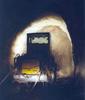
The pressure tunnel has a length of 1.2km and inclines 1:7 to the intake gate. The gates consisting of a roller gate (main gate) and a sliding gate (revision gate), are operated trough a vertical shaft (30m) to a gate house at terrain level on de banks of the reservoir (Holmavatn). Upstream of the gates the tunnel declines 1:7 down to a submerged inlet (under water piercing) below LRWL.
Sønnå hydro power project
As a result of the demand from NVE for the decommissioning of the forge-welded penstocks of Sauda I and Sauda III and the considerable age of the two plants, the possibility of adding the head of the two plants into one project was looked at. The project is currently under construction, named Sønnå power project. The project actually consists of two power stations in the same cavern, named Sønnå H (high) and Sønnå L (low). The cavern is situated about 1km into the mountain south of the city centre in Sauda.
Sønnå H) utilises the gross head of 550m from Dalvatn to the Sauda fjord. With a maximum discharge of 42m2/sec, Sønnå H will divert the water currently utilised through Sauda I and Sauda III directly from the reservoir trough the headrace system, turbine and tailrace to the fjord. The waterway consists of an approximately. 11km unlined headrace pressure tunnel (A=38m2), 85m embedded penstock (2 x Ø2.5m), turbine with draft tube and a roughly 1.3km long tailrace tunnel (A=60m2) to a submerged outlet at elevation -35m in the fjord. The power is generated by two Francis turbines of 102.5MW each.
For Sønnå H, an enlargement of the catchment is planned by means of four brook inlets directly via short raise drilled shafts onto the headrace tunnel itself, as well as two major transfer tunnels from areas further away. These two transfer tunnels are the Lingvang/Tengesdal transfer and the Maldal/Sagelva transfer. The first of the two will convert water from the Lingvang river and the Tengesdal river through a 9km transfer tunnel to the connection point with the headrace tunnel at Raundalen. To reduce environmental impact from the construction activity, construction of the tunnel is takingh place only from one end, namely Raundalen.
The two rivers Maldal and Sagelva will be diverted trough a 4km transfer tunnel, connecting with the headrace tunnel 1.5km upstream of the power house. In connection with the brook inlet in Sagelva, a surge chamber for the whole headrace system (Sønnå H) will be established. This consists of a 200m long horizontal tunnel (A=approximately 30m2) with an overflow wall at the entrance. The overflow wall is introduced due to the fact that the brook inlet in Sagelva is situated only 7.5m above the HRWL in Dalvatn (intake reservoir). There must be full control of the level of the upsurge, not allowing any overrun of the level of the brook inlet that would cause flooding out into Sagelva. There will be blockouts at the bottom to allow for controlled backflow of water after reaching the peak of the upsurge.
The Sønnå L plant will utilise the same head as Sauda III, but less water will be available. Water currently coming into Storlivatn reservoir via Sauda I will be diverted to the fjord through Sønnå H. Sønnå L will have a maximum discharge of 30 m3/s. A Francis turbine of 60MW is planned side by side with the two Sønnå H units. Sønnå L will utilise the old headrace tunnel to Sauda III. Just upstream of the surge tank and valve chamber in the existing headrace system, a new approximately 180m and Ø3.7m raised drilled shaft and short unlined tunnel will convert water to the new station. A 35m embedded penstock Ø2.5m will carry the water from the unlined pressure tunnel to the turbine. Sønnå L will share the same tailrace tunnel as Sønnå H.
Tendering and contracts
Even though ASS is a private entity, the right and responsibility given to it in the concession demands that rules governing purchase by government entities are followed. In this framework, the tendering and contracts were performed as negotiated contracts.
The evaluation was based on preset criteria given in the tender documents. All costs and benefits were converted to net present value to give a common basis for comparison.
To evaluate alternative solutions and varying distribution of costs in the tenders, a risk evaluation was carried out using a tipple estimate (low [roughly 1% percentile], the engineers best estimate and high [roughly 99% percentile]) on quantity combined with a Monte Carlo simulation to produce a S-curve (confidence vs. cost level) for each of the tenders.
Civil Works
In tendering for civil works the project was divided into five contracts for preparatory works and six contracts for the main construction works.
The contracts for the preparatory works were awarded to local construction companies, and the work was carried out in parallel with the contract negotiations for the main works. The work undertaken enabled a smooth start for the main contractors.
The contracts for the main works were divided as follows:
• B1 – Sønnå power station, including transfer Maldal/Sagelva and parts of the headrace system.
• B2 – Raudalen, including the headrace tunnel from intake in Dalvatn to the interception point with the B1 contract below Raundalsbekken. Furthermore, the contract includes the Lingvang/Tengesdal transfer tunnel. Brook inlets both on the transfer tunnel and the headrace tunnel are also included in this contract. For this tunnel it was asked for an option price for using a TBM instead of drill and blast. Two of the contractors gave such a price, and it was only at the end that the TBM alternative fell to the competition of the chosen contractor.
• B3 – Dalvatn power plant, including the building for the new unit, the new headrace system and new façade creating an improved architectural expression.
• B4 – Transfer tunnel from the Slettedal river.
• B5 – Transfer tunnels Istjønna and Reinsvatn.
• B6 – Small earth fill dam for diversion of the Tengesdal river to Risvatn.
There are no access roads to the construction sites for contract B4, B5 and B6 as well as the brook inlets included in contract B1 and B2. The work must therefore be based on support by helicopter.
The reason for dividing the work into so many different contracts was that the geographical spreading of the different worksites did not entail any cost benefits in awarding the whole project to one contractor. A division also enabled contractors with different skills and resource bases to be competitive. The result of the tendering did show that only one of the eight contractors bidding for the job included a cost reduction if awarded the whole project. Three of the contractors did not deliver due to resource shortage, size and the sheer complexity of the project.
The rest of the contractors delivered bids on parts of the project or the whole project. The competition was most tight for the B1 and B2 contracts. Some of the contractors awarded large discounts if both contracts were rewarded to them.
The contracts for the civil works are based on the Norwegian contract norm NS8405. The design is made by the owner (owner’s engineer). The contract is regulated based on actual quantities. Unit prices are given in the tender’s bill of quantities (BoQ). The contract framework was chosen due to the nature of the project. The risk in the civil contracts is first and foremost connected to geological conditions. Since the contractor has no significant control over these conditions, the risk is placed on the owner. The contract also allows for flexibility to adjust design during construction or changing demands.
The contractor is responsible for choosing rock support at the workface (for protection of the tunnel workers), whereas the owner is responsible for defining the permanent support. A reward was set to motivate the contractor to choose a moderate, but safe support level. The owner has at least one engineering geologist present at site to guide the contractor in choosing support level. Furthermore, a division of benefits following smart solutions presented by any of the parties involved, is included to motivate for creative solutions.
Electro mechanical works
The tender for the mechanical and electro technical works as well as hydraulic steel works were awarded through a similar process as described for the civil works. The contracts are based on a well established Norwegian contract norm for this type of work, namely AKB88. This norm is based on similar principals as the “yellow” Fidic norm.
Challenges so far
Location and orientation of the power house and transformer cavern to fit geological conditions
The location and orientation of the Sønnå powerhouse and transformer caverns were estimated based on geological surface mapping and aerial photos (stereoscopic study), as well as a Face II 2D FEM analysis to estimate the minor principal stress compared to the water pressure in the unlined pressure tunnel in the area of transition to embedded penstocks. The caverns were preliminarily placed inside an expected weakness zone some 1000m into the mountain along the access tunnel. It was recommended to pass this zone before performing hydraulic spit tests to verify in-situ stress conditions.
Favourable rock conditions were expected, except when crossing weakness zones. The conditions matched fairly well with expectations as the access tunnel was excavated until the tunnel was driven into a water carrying zone after roughly. 800m. Grouting became necessary. After crossing this zone conditions got better before reaching the expected zone in front of the station, after about 1000m. The zone was water infested and carried swelling clay, dealt with by means of pregrouting, spilling and reinforced shotcrete on lattice girders.
After crossing the zone, the engineers wanted to decide on the location of the caverns. The problem was that even though the rock conditions were getting better, several open cracks with high water pressure were encountered. After moving the location 80m from the position laid out in the tender design, a decision was made to start excavating the planned bypass around the power house and transformer caverns to the headrace of Sønnå H. At the same time, core drilling was undertaken in two directions (one crossing the powerhouse cavern towards the pressure tunnel of Sønnå H, and one along the axis of the transformer cavern). The drilling showed competent rock with crossing intrusion zones. The problem was that water was struck at unfavourable locations. In the borehole crossing the planned powerhouse cavern, the core drilling had to be stopped due to a leakage of about 400-600l/min through the hole driven by a pressure of approximately 25 Bar. This zone was also encountered in the hole drilled along the transformer house cavern.
Observations in the boreholes as well as in the bypass tunnel made it possible to estimate the location and direction of the zones in the area. From the geometry of the zones it became evident that the location and orientation of the cavern given in the tender design was not favourable. In a meeting between ASS and Norconsult it was decided that the whole complex (caverns and tunnels) should be rotated about. 400 counter clockwise with an apex point at the working front of the access tunnel (see Figures 9 and 10). This enables excavation of the caverns with a minimum of grouting and rock support.
Water problems in the transfer tunnel Lingvang/Tengesdal
The transfer tunnel excavated from Raundalen towards Lingvang (9km) struck water 740m in. Since then there have been severe problems with water under high pressure coming into the tunnel when puncturing zones or fissures crossing the path of the tunnel. The leakage has been up to 3-4m3 per minute from one single zone.
Even though the rock mass consists of massive granitic gneiss, the overburden pressure represented by 300-400m of rock above the tunnel is not sufficient to tighten the cracks. The problematic open crack system seems to follow the foliation in the direction of N60º-70ºW. The cracks open enough to give rise to water problems as often as every 20-40m. An explanation to the open cracks may be the fact that there is a fairly young (in geological terms) and massive fault zone running nearly parallel to the tunnel axis approximately. 1km east of the tunnel. This may have given rise to so called ‘Fieder-spalten’ (shear cracks), running with a 450 angel to the fault zone. There are indications on a change in structure roughly at profile 1700 (Figure 11).
In the meantime, work must be carried out with extreme caution. Exploratory drilling is currently carried out by two to four holes 20-25m in front of the workface. When water is struck, either by the exploration holes or when drilling for the excavation of the tunnel, pregrouting around the circumference of the tunnel is carried out. The problem is that the nature and orientation of the cracks is such that one may strike water between two earlier holes, even when the centre distance is only a couple of metres. In some cases this has given rise to leakage behind the workface, making it hard to establish backpressure when grouting.
Crossing a zinc ore with the headrace tunnel
Approximately 1.2km upstream of the construction in Raudalen, the headrace tunnel is crossing the border between two different rock formations. In this we expect to strike zinc ores. The ores have been mined in areas on both sides of the alignment of the tunnel for years.
Due to the toxicity of the substances found alongside the zinc, Norway’s authority on pollution (SFT) has put strict rules on the handling and deposition of zinc infested tunnel spoil.
A special depot is prepared for storing the infested material. It consists of a pool with an impervious membrane where the spoil is to be placed. After placing the spoil, it will be covered with a similar membrane of that placed under and sealed. Any leakage from the deposit will be collected and carried by drainage pipes through a manhole where water quality can be checked at frequent intervals.
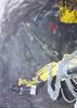
Upon entering the area where zinc is expected, exploratory drilling is carried out in 45m sections. A front piece is mounted on the gage to collect the process water and spoil from the drilling through a pipe into a bucket (as shown in the picture above). For each metre of drilling the content of the bucket is analysed, using a hand held device. The device is able to detect small amounts of zinc (and other substances) with good accuracy. The equipment was tested in the old zinc mines before the tunnel reached the area where zinc is expected.
Based on the findings from the exploratory drilling the excavation plan may be adjusted to fit the zinc zones. This will reduce the amount of spoil that has to be treated as toxic waste. A threshold of 1% zinc on a 1m section is preset as the amount that will trigger special handling.
Other challenges
Other challenges worth mentioning include:
• Finding an acceptable solution for a spoil deposit on land for the spoil excavated in the B1 contract (originally planned to be dumped in the fjord).
• Snow avalanche affecting the worksite at Nyggjelebeitevatn (contract B4).
• Handling scrap iron from the old power station at Dalvatn (contract B3).
• Establishing the plug where an underwater piercing will take place following the establishment of the intake gate at Holmavatn (contract B3).
• Evaluation and surge calculations in the headrace and tailrace system to Sønnå (contract B1). This also includes a salt water barrier in the tailrace system (utilising the difference in density between salty and fresh water).
• Weak rock zones in the Slettedalen transfer tunnel.
Design work and communication
This is a complex hydro power project with many contracts including design, manufacturing and assembly in geographically separated locations. A major success criterion is smooth communication and understandable interface documentation. In the Sauda project the process is oiled by an internet based communication platform called eRoom. eRoom is provided by joint collaboration. The information is communicated over the internet to a server in the client system (it may also be rented by joint collaboration). All written communication shall be canalised through this system. The system platform contains ‘rooms’ for (examples):
• Communications (such as letters, e-mail etc.)
• Discussion (linked communication which documents the design process)
• IDC database (formalised database for checking of interface information between the different contributors)
• Official drawing database
For the Sønnå power plant, Norconsult chose to go fully 3D when doing the design. All information is converted into 3D and imported into the main model (as a reference). This makes it possible to do crash tests in the arrangement of the equipment, piping and cable bridges etc.
Further on the production and quality assurance of block outs is made easier. The civil works model is made in Microstation Triforma. This application enables generation of plans and sections for production of 2D drawings as basis for the work at site. The 3D model is also communicated to the civil contractor as a support for planning and production.
Author Info:
The author is Øyvind Engelstad, of Norconsult. Email:oee@norconsult.no.
TablesTable 1 Table 2