Grouting works at Jinping
17 February 2009Since the first pressurised water inflows entered the east side of access tunnel B at the Jinping hydro project on 8 January 2005, efforts have been undertaken to seal the flows through grouting. Ziping Huang and Shiyong Wu introduce some principles of the post-grouting work, including equipment and grout mixes, classify the water inflows and conducting zones, and present details on the post-grouting works carried out in the west side tunnels
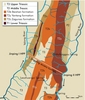
The 17.5km long access tunnels for the Jinping hydro scheme are located in the Jinping Great Bend region and consist of two parallel (twin) tunnels spaced 35m apart (axis to axis) (Huang and Wu, 2008). Their construction has allowed traffic from the Jinping I and Jinping II hydro projects to avoid 138km of roads located in steep valleys often subjected to earthquakes, and allows for more convenient communication between the two projects. Passing beneath the Jinping mountains, the tunnels have up to 2500m overburden and are mostly located in limestone and marble (see Figures 1 and 2 and Table 1).
A 4km long test adit excavated before the tunnels’ construction experienced large water inflows from the combination of faults and karst cavities, making it clear that the access tunnels would likely encounter similar large inflows. Originally, probe drilling was to be carried out to discover any water-conducting structures, which would then be grouted prior to construction of the twin tunnels. During excavation, however, it was decided that the water bearing zones would be filled later – the water would be drained and post-grouting would be carried out once the inflow and pressure had reduced. The main reason for this is the fact that the tunnels are twin tunnels – one was expected to act as a drainage tunnel with the other for transportation and removal of blasted debris.
However, the many inflows experienced in the tunnels led to severe problems with the excavation work, delaying construction. In some areas the inflows did not reduce as much as assumed, with post grouting work proving difficult. An earlier paper on the water inflows at Jinping was published in the October 2008 issue of International Water Power & Dam Construction, where the authors described the inflows and related geological structures – and the change in strategy in dealing with the inflows. This new paper is an attempt to characterize the water inflows and the water bearing zones, and introduces the principles, key equipment and grout materials found useful in sealing the cavities and faults.
Water inflows at Jinping
Types of groundwater inflows encountered
During excavation, the twin tunnels experienced large water in-bursts and gushing water. Before break-through of Tunnel B in May 2008 and Tunnel A in August 2008, inflows in the east side tunnels had accumulated up to 7m3/sec (Huang and Wu, 2008). After the first water in-burst on 8 January, 2005 – when the east side of tunnel B had been excavated to about 3055m – efforts were made to drain the water and seal inflows through post-grouting. These post-grouting works are still being carried out, becoming more effective over time.
Of the many water inflows that were encountered at various locations, there were 11 significant water in-bursts with more than 200L/sec entering the tunnels (Huang and Wu, 2008). The water came from joints, joint zones and faults, often karstified to form channels and cavities, with almost continuous water flow.
Sometimes the blast holes were so close to the water bearing zone, that the blasting actually encountered the water. Or, after blasting, the pressurized water in the cavity split the fractured rock masses and burst into the tunnel. The statistical data shows that, quite often, water inflows with a large volume and high pressure occurred at single locations. Based on the difference in flows, the water inflows may be classified as follows (Norconsult Report No. 3, 2004): a) Seepage for volumes < litres/day; b) Dripping for volumes of litres/day to m3/hour; c) Water inflow for volumes of m3/hour to many m3/minute; d) Water in-burst for volumes > many m3/sec; e) Gushing water or jetting water for pressurized inflow of water many litres/sec.
Water-conducting zones
According to geological investigations and observations carried out, the surface water enters into the ground through faults and fissures in the soluble and brittle carbonate rocks which, over time, developed karst phenomena like open joints, channels, and even large cavities. The high water pressures – sometimes more than 8MPa – caused severe problems for the tunnel excavation works.
Table 2 shows the estimated lengths of rocks in the main geological units along the twin access tunnels. In the Zagunao formation in the west side of Tunnel B, in the section BK2+683-BK2+696m and the tensile fissure zone striking N65~80°W, a karst cavity about 15m long, 5-6m wide and a maximum 20m high was observed after a water in-burst occurred. The cavity developed along the strike direction of the rocks and in the direction perpendicular to the strike of the fissures. The water inflow reduced quickly due to the existence of dissoluble rocks of schist, shale and sandstone that probably prevent large networks of water channels in the marbles, limiting water supply in this region. In the Baishan formation, there are rich water bearing zones with continuous water supply through the channel networks developed as karst channels in the soluble rocks. Although the joint width should have reduced due to the increasing overburden pressure, the very high water pressure has probably prevented this.
Considering the behaviour of water inflow, how fast the pressure and inflow drops down, and the structural composition of water conducting formations, the water bearing zones in the rock may be characterized as: a) Normal water bearing zone (total inflow of 0.5-20L/sec in a 30m long tunnel section); b) Zone of large inflow (total inflow of 20-100L/sec in a 30m long tunnel section); c) Zone of very large water inflow (total inflow of 100-1000L/sec in a 30m long tunnel section, water pressure greater than 1MPa); d) Zone of extremely large water inflow (total inflow larger than 1000L/sec in a 30m long tunnel section, water pressure greater than 1MPa); e) Large water inflow from karst channels or cavities.
Methods for post-grouting the water
The ground water conditions at Jinping are more difficult to handle than in most tunnels, with pressures more than 8MPa and large karst cavities and inflows of several m3/sec to be sealed. It is uncertain whether a successful result, even with the most modern equipment, materials and experience, will be possible within a reasonable time. A positive effect of the ground being drained before grouting is carried out is a potential reduction of the water pressure and magnitude of the inflowing water.
This is particularly important for the construction of Jinping II hydro project’s headrace tunnels, which run parallel to the access tunnels.
Principles
Grouting is an art. It involves many conditions that interact, including rocks, joint network and characteristics, geometry, and water pressure. To ensure a good result, sealing work must be planned in advance, considering introductory works (such as drainage) and the grouting works including placing and length of grout holes.
When grouting, it is important to note that flowing water cannot generally be grouted through common methods, as the grout material will be washed away by the water flow. Therefore, the work has to be tailored to the site conditions, using the correct type of grout to achieve a successful sealing result within a reasonable time.
• Small inflows of water with low pressure can often be plugged by rapid-hardening cement mix.
• Large inflows of water with low pressure must generally be drained or plugged first. Liquid polyurethane that turns to foam when in contact with water has sometimes been used.
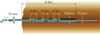
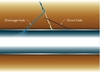
• Large inflows with high pressure, jetting water must be stopped using solutions specially adapted to the actual conditions. Such work is most often difficult and time-consuming. There is no general rule on how to do these works. A strategy needs to be evolved which looks at the type of grout and the grouting pressure, as well as the placement of grout holes and drainage holes. A method for this is to plug the tunnel and then perform the grouting, as shown in Figure 3.
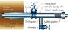
Temporary drain holes may be used to divert the water flow, as shown in Figure 4. For large water flows, several large drain holes will be necessary, or sometimes a small adit with drain holes should be used. The zone to be sealed deep around the tunnel should be 6-8m in order to withstand the high water pressure.
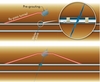
As the water-conducting zone may have large openings to fill with grout – particularly if the zone contains material of which large quantities have been washed into the tunnel – the use of a by-pass tunnel is an alternative to the grouting (Figure 5). For such a tunnel, the zone will have to be pre-grouted before it is excavated to avoid another water in-burst. However, in the access tunnel, a deviation of the tunnel alignment from straight line is not a good solution. Another method could be to plug the tunnel temporarily to handle the flowing water in order to perform grouting. The plug can then be removed by blasting, as shown in Figure 3 (Norconsult Report No. 6).
Grouting equipment
Drilling jumbos should, preferably, make the grout holes. A modern jumbo can drill more than 50m long holes. To achieve an efficient grouting execution, a grouting rig with grout container, mixers, agitators, pumps, etc. mounted on a rig is a good solution. Not only is it easy to move a rig to and from the site through the use of a lorry, but an efficient grouting rig could also have the potential to grout two or more holes simultaneously.
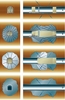
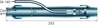
Key equipment developed specifically to handle the high pressure water is recommended. The sketch in Figure 6 is a special packer intended for use in situations with high water pressure. It is designed by AMV (Andersen Mek Verksted AS) in Norway. This packer may be useful when it is not possible to insert a standard hydraulic packer into the hole due to the high pressure of the gushing water, even with the use of the rod handling equipment. A standard hydraulic packer may have an inner diameter of ~1/3 of the outer diameter, so the gushing water will give strong resistance against the insertion.
The packer in Figure 6 is designed with an inner diameter equal or larger than the diameter of the drill hole for grouting. The packer is placed in a 102mm hole, which is drilled 3-5m before the probe or grout hole is drilled. In cases where high pressure water is encountered in the hole, the packer can be inserted into the larger drill hole, as the gushing water may pass inside the packer.
Figure 7 is an example of a blow-out preventer used for drilling of grout holes in a difficult high pressure grouting job in Colombia. The device is cast into the rock (as an orifice pipe), before the grout hole is drilled. It can be manufactured of available parts. For the Jinping access tunnel the cement anchorage should be placed deeper into the rock, e.g. 2-5m depending on the rock mass conditions.
Grouting materials
• Cement – ordinary Portland cement can be used in the Jinping access tunnels. Additives of superplastisizer, microsilica slurry or other materials to increase the cohesion and reduce shrinkage are strongly recommended. In addition, additives to accelerate hardening (for blocking the grout penetration) will often help in achieving a good result.
• Polyurethane – This is used as a grouting material for high flowing formations and as a plug-grout in grouting holes and for post. The material expands 15 times or more when it comes into contact with water.
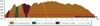
• Blocker grouts – It is sufficient for a 5-10m zone around the tunnel to be sealed by grouting. Where larger water channels occur, the grout tends to float much longer distances than that, meaning that large volumes of grout are pumped through a grout hole without any pressure to build-up. To prevent this excess of grout consumption, blocker systems have been developed over the last 5-10 years (see Figure 8). The principle is that a specially designed cement-based grout hardens at a pre-set time after being injected, blocking further penetration of the grout through that channel. Proper use of a blocker will significantly reduce grout consumption and the time needed for grouting.
• Colloidal silica – Also called silica sol, this is an alternative to cement-based materials. It is an aqueous dispersion of discrete colloid amorphous silica particles. The properties of silica sol, such as the gelling time, can be changed with different proportions of the added saline solution. The gelling of Silica sol is determined by the amount of salt added to the mix. The strength of silica sol continues to increase for a long time and is linked to the relative humidity. There are several commercial products of silica sol available.
Additives to cement grouts
For the Jinping access tunnels, one of the challenges is finding a suitable grout mix to penetrate and fill water channels along joints or faults of varying sizes, which are subject to high water pressure. To cope with these conditions the grout must have the following properties:
1) It is stable, i.e. < 5% sedimentation (bleeding) after 90-100 minutes.
2) It has little shrinkage during hardening, so no open parts will develop along the rock fissure walls.
3) The hardened grout has an acceptable strength, low water permeability, and high bond strength.
4) It has good internal bonding so the grout does not disperse as it penetrates, but replaces water as it moves through the water channels.
In order to achieve the first three requirements, thick grouts with additives were used early on. In the beginning, bentonite was used as additive, but, as has been shown in many published papers, bentonite reduces the quality of the grout. Other additives are more suitable for changing/improving the properties of grout.
The most common additive today is superplasticizer, which is used to increase the flow of the grout and improve mixing (dispersion). However, the grout still has to be thick for the mix to be stable (water /cement ratio (w/c) < 0.7).
The use of microsilica as an additive gives the grout better cohesion during its travel trough the water channels. Thus, less grout will disperse. As the microsilica creates less shrinkage, the grouting will be more effective. The best result using microsilica can be achieved with silica slurry. Normal dosage of microsilica is 10-25% of the cement weight.
There are different suppliers for grouting materials. The selection is a matter of the site conditions, the experience of the grouting personnel as well as the economical aspect. Some manufacturers are BASF, Switzerland, Mapei, Italy and Rescon Mapei, Norway, Elkem, Norway and Sika, Switzerland. Some manufacturers offer on-site advice from staff with considerable grouting experience.
The post-grouting works
Planning
The following work schemes are applied during the post-grouting of water inflows to different water bearing zones in the west side access tunnels:
• a) In the normal water bearing zone, for linear water inflows at a single location with volume between 1.0-5.0L/sec, seal some of the concentrated water flow from the rock mass discontinuities by post-grouting. Alternatively, install a drainage hole to divert the water to a drainage ditch, then apply shotcrete layers 30-40cm thick (C25).
• b) In the rich water bearing zone, seal the concentrated water flow from the rock mass discontinuities by post-grouting. Then apply consolidation grouting to the whole section to ensure a reinforced rock ring at least 6m thick.
• c) In the very to extremely rich water bearing zones, firstly drill holes and install 1-3m long steel pipe of diameter 50mm to grout cement or cement mix with sand and special additives, in order to ensure the water inflow within the 1-3m deep rock is kept under control. Secondly, drainage holes are drilled to divert water and release the water pressure as shown in Photo 3. Consolidation grouting is then implemented 3-6m deep into the rock. Depending on the rock layer conditions, the drill hole will normally have diameter between 42mm-130mm, with depth approximately 6.5m. After this is completed, post-grouting will seal the drainage holes. Grouting material is mainly cement, with additives.
• d) In the karst channels or the zones which have experienced water in-burst, apply one or more of the following sealing technologies: plastic bag grouting, plastic purse grouting and special grouting material. Alternatively, the tunnel can be plugged to allow grouting to be performed, as illustrated in Figures 3 and 4.
In cases b), c) and d), consolidation grouting should be carried out in order to form a reinforced rock ring to prevent high pressure water from jetting into the tunnel. This will also improve the stability of the surrounding rock masses and thus ensure the safety of the tunnel. The grouting holes are arranged alternately with spacing 2m along the periphery and in the tunnel axis direction. The parameters are listed in Table 3. At locations with large volume of water inflows, the number of grouting holes may be increased. The grouting material used mainly includes ordinary Portland cement or cement sand.
Special additives to cement are added to improve the properties of the grout. This mainly includes inert fibre and material to accelerate hardening and reduce the water volume. The grouting pressure is about 1 to 2 times the water pressure.
Methods used for post-grouting of large water inflows
The post-grouting method of large water inflows is as follows:
• 1) The grouting holes were placed to intersect the discontinuities.
• 2) 6m long grouting holes with diameter between 42mm-150mm were used. The number of holes were adjusted according to the water inflow.
• 3) Grout nipples made by pressure steel tubs with diameter of 50mm-150mm and length of 1-3m were adapted with special additives and the blow-out preventer at locations with high water pressure and large volume water inflow.
• 4) The grout mixes were chosen to fit different conditions of water inflows, including: normal Portland cement with water/cement ratio (w/c) = 0.5:1 (or even thicker grout when needed); cement with sand and a special environmentally-friendly additive suitable for use in flowing water with the setting time adjusted for the water inflow conditions; and a special grout designed to cope with the high water pressure, speed, and short set time.
• 5) The grout is pumped. When using two grouts, the type of mixing depended upon the water inflow conditions: i.e. mixing either inside the hole or at the borehole collar.
• 6) Generally, the grouting pressure was about 1 to 2 times the water pressure. To ensure the stability of the surrounding rock masses, the initial pumping pressure was set to 3MPa and then adjusted during the grouting.
• 7) When the grout consumption was less than 5L/min under the designed grouting pressure, the grouting continued for 10 minutes before being stopped.
A process to check the quality of the grouting was developed, including pictures of the grouting section before and after grouting, and measurement of the difference of the water inflows.
Zones with very and extremely high water inflows
The method for treatment in sections with very large gushing water in-burst was to use a combination of the described post-grouting with drainage. After initial drainage and grouting, the rock masses were reinforced by rock bolting, and shotcrete or concrete lining or wall. Finally after plugging the drain holes, high pressure grouting was carried out along the whole section with inflows.
Some practical issues here are:
• When the water pressure is too high to insert the expanding packer, a grouting hole should be drilled at the location near the water inflow but not affected by it. The hole should be drilled into the water bearing zone with the diameter relatively larger. The blow-out preventer should be installed. Additional drainage holes may be drilled should it be necessary.
• The fractured tunnel section should be reinforced by systematic rock bolting normally spaced 1m apart, 4.5m long with a diameter of 25mm and consolidation grouting. At locations of serious fractured rock masses, install wire mesh reinforced shotcrete or steel rib.
• Grouting should then be carried out. while monitoring the deformation of the rock masses. Water inflows should be measured in the whole zone. The quality of the grouting should be checked.
Karst channels and cavities
For these cases it is necessary to carry out investigations of the actual area, using probe drilling and suitable geophysical methods to map the locations of the channels and cavities, Grouting should be planned for the results. Special techniques using plastic bag grouting, plastic purse grouting and special grouting materials are applied. In large cavities it may be necessary to use concrete or cement mortar to fill the openings. Finally high pressure grouting should be carried out to reinforce the whole zone, with the quality of the grouting checked in the same way as described before.
Results of the post-grouting
The water sealing work at the west side of the access tunnels started in July 2006. Up to 2 August 2007, the total length of zones with large inflows that has been sealed by post-grouting is 706m. The total steady water inflows here were reduced from 3m3/sec to 1.3m3/sec. The detailed reduction at locations is shown in the Table 1 and Table 2 in the paper included in the October 2008 issue of this journal.
Discussion
If a zone with large, gushing water remains undetected, extensive flooding can obviously occur in the tunnels. Such an event can bring large quantities of mud, sand and rock debris into the tunnel, which would then have to be removed once the flow has reduced to an acceptable volume. Fortunately for the Jinping scheme, it has twin tunnels with connecting tunnels, and one of the tunnels can be used to convey the water while the excavation works continue in the other.
The twin Jinping access tunnels have been excavated through very large gushing inflows, the largest being at BK2+637 of 15.6m3/sec. The tunnel workers have done a great job working in such very difficult ground conditions.
In a previous paper the shifting of strategy from water forecasting and pre-grouting to post-grouting was discussed for the Jinping access tunnels (Huang and Wu, 2008). As mentioned, using one of the access tunnels for drainage made the shifting possible and it will also help reduce water problems for the four headrace tunnels under construction at the Jinping II hydro power project. To keep the drainage, a special drainage tunnel excavated by TBM will finally replace the access tunnel. As a result, a major task has been initial post-grouting of the larger inflows following drainage. Much experience has been gained during these works, with the effect of post-grouting increasing considerably and even difficult sealing works have been successful.
There is not yet a report on the ongoing sealing of large water inflows at the three locations Ak14+762, Ak13+878 and AK13+520. Regarding construction of the headrace tunnels, it may be more effective to divert the water into the TBM drainage tunnel. For the ongoing works on the headrace tunnels the impact and risk from ground water inflows is probably lower, as the pressure and consequently the rate of inflow will be reduced.
It may be argued that the post-grouting approach caused the delay of construction – but this delay is much less than what it would have been had there been a single tunnel. The post-grouting approach does increase the safety risk to the crews and equipment, but this risk is considerably reduced with twin tunnels, where the crew and equipment can stay in the other tunnel during blasting.
Ziping Huang, Ph.D, Norconsult AS, Sandvika, Norway and Shiyong Wu, Ph.D, Ertan Hydropower Development Co (EHDC), Chengdu, China
The authors are grateful to Dr Arild Palmstrom for his contribution in review and modification of this paper based on his work throughout the consulting service for the design and construction of the Jinping Access Tunnels
TablesTable 1 Table 2 Table 3