Renovation success
12 April 2006Urban encroachment, design flaws, and a history of slope and outlet works deformations meant a comprehensive renovation programme was needed at Standley Lake dam. Joseph M Green-Heffern and James R Schneider describe how the US$40M improvement project was completed ahead of schedule and came in under budget
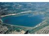
A large Colorado farming community and three cities with over 250,000 people rely on the 95-year-old Standley Lake dam for water supply storage. Standley Lake is located in the northwest Denver metropolitan area, and is an off-stream reservoir that stores mountain snowmelt delivered via canal from Clear Creek near Golden, Colorado, US.
The dam and reservoir are situated in a high plains environment about 8km east of the Rocky Mountain front. The surrounding and downstream areas were predominantly rural up until the 1970s. Since then, much of the surrounding area has become urbanised, although there is dedicated open space and a regional park at the reservoir that provide for boating and other recreational uses.
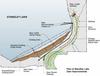
The 1.6km-long, 27.4m-high Standley Lake dam was built between 1909 and 1911 to store irrigation water for farmers. The dam is owned by the Farmers Reservoir and Irrigation Company (FRICO) but operated jointly with the Cities of Westminster, Northglenn, and Thornton, Colorado (the Cities). Founded on a ‘weak’ clay shale formation, the dam was constructed by dumping fill from railroad trestles, filling with teams, and sluicing claystone particles into a ‘puddled core’ (Figure 1). Major slope failures occurred shortly after construction, causing the dam to remain unused until after World War I. It was then repaired and placed in service by filling to an elevation about 6m below the originally planned crest elevation, which provided approximately 25.9Mm3 of storage.
The dam and reservoir were enlarged in 1964 to the original design reservoir capacity of 53Mm3, with the increased storage available for municipal use. Downstream slope movements and crest cracking in the 1970s led to the addition of a downstream stability berm along the dam toe except at the outlet works. Despite the addition of the berms, the pressurised outlet conduits beneath the dam exhibited evidence of elongation, presumably due to soil creep in the foundation causing embankment base spreading. Leaking conduit joints were repaired by using interior seals, and post-tensioned anchors were constructed at the valve house in an attempt to limit movement. However, as time passed, these anchors began to fail.
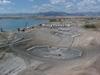
In 1996 an independent Board of Review concluded that renovation improvements were needed on a high-priority basis because the dam lacked sufficient defensive or ‘robust’ design features to resist progressive failure by linked failure mechanisms. For example, urban encroachment increased the risk posed by the dam while constraining room to construct features to respond to problems (Figure 2). The State Engineer also required that the spillway capacity be increased to meet current standards.
Key features of the renovation
Standley Lake serves as the sole water supply for FRICO and one of the cities, and the primary water supply for the other two cities. Renovation improvements had to be constructed during a prolonged drought and under conditions of population and demand growth in the cities. For these reasons, the construction was designed to be performed without lowering the reservoir. The necessary improvements had to be accomplished concurrently on a prioritised basis to speed all needed safety upgrades but in a paced manner that provided for careful management of project costs, construction risks, and impacts to water supply, recreational users of the lake, and suburban neighbours. The improvements to Standley Lake dam consisted of four key renovation features described below and shown in plan on Figure 3.
Constructing a new outlet works without draining the reservoir
The new outlet was built through the left abutment to remove it from beneath the dam embankment. The outlet consists of two 183cm-diameter intakes constructed using microtunnelling technology with underwater wet-recovery of the microtunnelling machine, a new 259cm-diameter outlet conduit installed via conventional tunnelling through the rock abutment, and a new valve house and pipe connections to the existing water supply system. A schematic profile through the new outlet works is shown on Figure 4.
Abandoning existing outlet works without draining the reservoir
The existing outlet works could be abandoned in place only after the new outlet works were operational. The four 183m-long, 122cm-diameter outlet conduits were abandoned in-place by filling them with concrete grout to prevent future collapse. The grout was injected into each conduit from the downstream end against the full reservoir head. Protective filter drains were installed to collect and safely discharge any future seepage along the conduits. The downstream valve house and adjacent piping were demolished and removed.
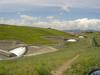
Constructing a new enlarged spillway
Concurrent with construction of the new outlet works, a new larger spillway was built to pass the inflow design flood resulting from 100% of the Probable Maximum Precipitation (PMP). The control structure is a ten-cycle, reinforced-concrete labyrinth weir. A trapezoidal earth spillway channel includes a series of RCC drop structures. A riprap-lined low-flow section conveys storm flows up to twice the flow from the 100-year storm event without appreciable erosion damage. Larger discharges will be conveyed in the earth-lined portion of the channel, with some level of erosion damage requiring subsequent repair.
Constructing an expanded downstream stability berm
The existing downstream stability berm was enlarged using 993,980m3 of material excavated from the new spillway to provide passive resistance to stabilise the dam and foundation from further deformation and potential sliding failures. The berm included filter drains to safely collect and discharge embankment and foundation seepage.
Problems to overcome
Implementation of the renovation improvements required overcoming a number of difficult problems and challenges, including:
• Addressing major safety concerns related to facility age, conditions, and especially ongoing outlet creep.
• The need to keep the reservoir in operation throughout construction, which required marine work including deep wet taps and careful coordination for pipe connections.
• The presence of swell-susceptible soil and bedrock, which had the potential to impact shaft sinking, tunnel construction, and especially the microtunnelling.
• Limited work space due to urban encroachment within 91.4m of the dam toe and 30.5m of the spillway.
• Coordinating among a large group of stakeholders.
Solving challenges
Some of the design and construction techniques that contributed to successful renovation included the following:
• Microtunnelled wet taps were used for new intake conduits. At over 381m in length, the lower intake was the longest wet tap of this diameter (182cm) yet constructed.
•The prefabricated intake structures were designed for easy installation and fit-up with the microtunnelled pipes under poor visibility conditions in deep water. This design was adapted from off-shore petroleum industry construction techniques.
• To safely abandon the existing outlet works without lowering the reservoir, each conduit was grouted in a single operation against full reservoir head, using approximately 214m3 of grout per conduit.
• A performance-based spillway design was selected to balance construction cost with a degree of tolerable erosion damage across a range of hydrologic events, including frequent flows, one and two times the 100-year storm event, and the Probable Maximum Flood event. The 1.6km-long spillway also required two major curves to accommodate downstream urban encroachment.
• The contractors used a number of innovative construction techniques, including custom jump forms for the shaft lining, remote-control transit buckets for RCC placement, and concurrent construction of the intake conduits and outlet tunnel. The concurrent construction of the tunnels was accomplished by using a temporary bulkhead at the upstream end of the outlet tunnel to prevent reservoir loss in case of intake failure during microtunnelling.
Teamwork and organisation
To both guide and deliver this US$40M project, FRICO and the Standley Lake Cities hired a local engineering consulting team that brought the combined technical and project delivery expertise needed for this difficult and multi-faceted project. Beginning with planning in 1999, during design and permitting in 2000 and 2001, and through bidding and construction in 2002 through 2004, this engineering team worked closely with other members of the overall project team to assure seamless project delivery. Members of the project team included the following:
• Owner: Farmers Reservoir and Irrigation Company.
• Municipalities: The Cities of Westminster, Northglenn, and Thornton.
• Engineering Team: CH2M HILL, GEI Consultants, and Tetra Tech RMC.
• Contractors: ASI RCC/R.E. Monks, a Joint Venture.
• Outside Board of Review: Don U. Deere, Art Strassburger, Alfred Hendron.
• Owners Representative during Construction: J.A. Cesare and Assoc.
• Independent Constructability/Cost Review: Joe Kellogg and Assoc. and R.W. Beck.
The key regulatory agencies for the project were the Colorado State Engineer’s Office (SEO) and the US Army Corps of Engineers.
Engineering team
The engineering team was organised to combine a national firm with deep project delivery resources as well as marine, lake-tap, and other specialised expertise, with two local firms having local underground and dam engineering expertise. As prime consultant, CH2M HILL provided project delivery leadership, permitting, and environmental services, and was responsible for overall engineering of the new outlet works as well as detailed engineering of the reservoir intake structures and downstream control structures. Tetra Tech RMC was responsible for underground shaft and tunnel work and conveyance piping. GEI Consultants was responsible for the new spillway, embankment stabilisation berm, and abandonment of the existing outlet works.
Clear vision and continual endorsement of project direction
While there was a general awareness of the need to address safety deficiencies at Standley Lake dam, the urgency of the needed improvements was not as clearly understood. The ongoing embankment deformation and outlet conduit seepage/elongation problems had been addressed on an interim basis and were being monitored, but while the SEO had expressed concerns about these problems during annual safety inspections, they had only mandated an enlargement of the spillway for increased hydrologic capacity. Neither the SEO nor the owner’s engineering consultants could quantify the operational condition or safety of the outlet conduits, either in terms such as a factor of safety, predicted end of service life, or probability of failure.
Accordingly, FRICO and the Standley Lake Cities were planning to make needed improvements as part of a potential future enlargement. However, in initial planning studies for a possible enlargement it became apparent to the engineering consultants that the service life of the outlet conduits was a significant dam safety concern that should be addressed on a priority basis independent of any future enlargement.With FRICO and the Cities each having different budgetary and procedural constraints, and with a joint facility operating agreement that required unanimity for any capital expenditures, it became difficult to reach consensus on the scope, cost, and timing of necessary repairs. These concerns were addressed by developing a clear vision of the needed work and providing a framework for continuous review and endorsement of the project direction. This was achieved by the following:
• An independent Board of Review (BOR) with three highly experienced members of international reputation was retained to evaluate the need and urgency of necessary repairs. After confirmation of the need for priority repairs, and the general scope and methods for repair, the BOR remained involved to provide oversight and guidance during implementation of the improvements.
• The engineering team worked with FRICO and the Cities to articulate the following vision statement: Project Vision - Safe, timely, and cost-effective renovation work to enhance the safety of Standley Lake dam, so that it complies with Colorado dam safety requirements, and so that it can continue as a reliable water supply reservoir for the next 50 to 100 years.
• The engineering team worked with the Cities to provide a fair allocation of project costs among the Cities based on prior agreements and on a transparent articulation of work elements and associated costs
• FRICO and the Cities developed a special intergovernmental agreement (IGA) that established leadership, funding, decision, and communication protocols that would govern project implementation. At the suggestion of the engineering team, the IGA included provisions for an owner’s representative to facilitate decision-making during the construction phase.
• For the five-year duration of the project, FRICO, the Cities, and the engineering team met on a monthly basis and utilised structured meeting minutes, progress reports, and a project team website to provide an open, structured, and efficient framework for communications and decisions.
• Interim design review points provided FRICO and the Cities the opportunity to manage the scope and costs of the improvements.
• The use of a shared, private website allowed exchange of electronic documents and drawings, and storage of all deliverables for access by all owner staff. In addition, a public website to share general project information with the community was provided at http://projects.ch2m.com/Standley_Public/default.asp.
• Implementation of a formal, facilitated partnering process to encourage teamwork between the expanded project team.
Comprehensive risk management strategy
While no particular aspect of the project was new, the combination of construction technologies, the inherent risks of changed conditions with underground and marine work, the uncertainties associated with record setting microtunnel drives and grouted conduits, and the safety and operational risks of a live reservoir in an urban environment all drove the need for a comprehensive risk management strategy. Key elements of this strategy are:
• Commitment to the use of highly qualified team members with relevant expertise.
• Purchase of an owner-paid, project-specific, professional liability insurance policy.
• Utilisation of a Geotechnical Baseline Report to provide a clear basis for bidding and a fair allocation of risks for unforeseen conditions
in the underground work.
• Escrow of bid documents.
• Bidder attendance at a mandatory pre-bid meeting, a mandatory site walk that included excavation of test pits in the spillway alignment, and mandatory viewing of all of the rock cores from the tunnel alignment borings.
• Selective and limited specification of only a few key mandatory work sequences and methods – primarily the lake tap and downstream tunnel sequence; inclusion of an intermediate microtunnel jacking station for the lower, longer drive; and conduit grouting in the wet.
• Selective inclusion of provisions for bidder choice items and provisions for review/acceptance of contractor VE proposals.
• Inclusion of minimum qualifications for key construction specialties such as microtunnelling, conduit grouting, and RCC.
• Use of formal construction partnering.
• Provisions for an owners representative to facilitate timely decision-making with multiple owners.
Delivery approach
In March of 2000, during design, a construction budget of US$39.9M was established that consisted of a base construction estimate of US$34.7M plus a contingency amount of US$5.2M. In May 2002, six bids were received, ranging from a low of US$30.6M to a high of US$34.4M; the second and third low bids were within 2.1% of the low bid. Construction was completed over 28 months from mid 2002 through late 2004; this duration was two months ahead of the original 30-month schedule. The final construction cost was US$32.5M versus the base bid of US$30.6M, an increase of 6.1%. Of this, 3.2% was due to unit price quantity changes, 1.2% was due to owner-requested enhancements, and 1.8% was due to Change Orders required to adapt the design to the actual conditions disclosed. The final cost was US$2.2M (6.3%) less than the base construction estimate and US$7.4M (18.6%) below the construction budget. Contractor-proposed Value Engineering changes provided a total of only 0.1% in savings. The tight grouping of bids, the small amount of changes on such a complex project, and the small amount of VE savings all confirm efficient design and effective risk management.
Successful completion
Designed and constructed between 1999 and 2004, the US$40M Standley Lake dam improvement project could be considered a milestone in urban dam engineering. The project required technically-difficult improvements at a constrained urban site while maintaining uninterupted water deliveries. This was accomplished by carefully integrating a variety of design and construction approaches, including microtunnelled wet taps, conventional underground shaft and tunnel work, large-diameter piping and valves, marine construction, conventional and roller-compacted concrete, high-volume conduit grouting, earthmoving, and instrumentation and control systems. The project was completed ahead of schedule, under budget, and without claims, significant injuries, or litigation. A large number of parties worked closely and cooperatively for years to provide success on this project.
Author Info:
Joseph M. Green-Heffern, P.E., is Vice President and Senior Project Manager with GEI Consultants, Email: jgreen-heffern@geiconsultants.com. James R. Schneider, P.E., is Vice President and Principal Technologist with CH2M HILL. Email: jschneid@ch2m.com
This article was printed with kind permission of the Association of State Dam Safety Officials. For further information, please visit www.damsafety.org.