Storage solutions
17 January 2006E C Kalkani and P Foteinopoulos suggest that building two auxiliary dams and reservoirs could increase storage capacity at the Marathon dam project in Greece
The Marathon dam and reservoir in Greece is the oldest water storage structure for Athens’ water supply system. The research described in this paper presents the two major possibilities of increasing the storage of the Marathon reservoir by building two auxiliary dams and reservoirs, within the watershed of the existing dam. The areas and the volumes for the auxiliary storage reservoirs and dams are produced numerically and plotted to give an easy tool to the planning engineer on selecting the appropriate height of each dam, while also considering other factors affecting the planning stage of the design.
The proposed auxiliary dams and reservoirs in this research will serve not only for domestic water storage, but also for other uses of water such as recreation and irrigation, and for the development of the environment and the aesthetics of the region. Further research will refer to the enrichment of the Marathon reservoir by developing dams and reservoirs not only within the Marathon watershed but within neighboring watersheds as well, and by researching alternative positions of possible dam sites.
Description of the region
The Marathon dam and reservoir was the first large storage reservoir built specifically for the water supply system of Athens in Greece. The dam is located northeast of Athens at a distance of 45km, and west of Marathon, an ancient town in the valley of Marathon where the battle of Athenians against the Persians occurred in 490 BC. After the battle a messenger returned to Athens to announce the victory, running a distance of 26.2 miles (42.2km). It is as a result of this event that the world renowned ‘Marathon’ race was established.
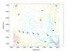
The water supply system for Athens was very small in 1922, and not adequate for the growing population. US-based ULEN was asked to prepare the design and supervise the construction of the first storage reservoir for domestic water supply – the Marathon dam. The dam is located on the Charadros river, which exits to the Marathon valley and towards the sea with a southeasterly direction. The watershed of the Charadros river is shown in Figure 1. This watershed is within the prefecture of Attica, and is located in the northeast of Athens.
Auxiliary reservoirs were originally planned to collect the flow from the surrounding mountains and then divert the water to the Marathon reservoir, which would act as the reservoir from which the water is transported to the Athens purification plants for domestic use.
However, plans to develop other reservoirs around Marathon were not eventually realized, because the rapidly growing population of Athens required greater quantities of water. Instead, the Yliki lake water (1959), the Mornos river water (1981) and the Evinos river water (1992) were carried either to the Marathon reservoir or directly to the drinking water purifications plants of Athens and Piraeus through an interconnected system of conveyance structures (http//www.eydap.gr).
Hence, since the dam was first constructed (1926-1929), no other refurbishment of the structure or projects to enrich the storage capacity of the reservoir were attempted.
The first water supply company established for the city of Athens was called the Greek Water Company (EEY) which was formed as a consortium of the Greek Government, the Bank of Athens and ULEN in 1925. The main purpose of the consortium was to raise money by issuing a bond and to develop and operate the water supply works for Athens.
In 1974 however, ULEN withdrew interests in Greece and left the operation of the water supply of Athens to the rest of the partners within the consortium. In 1980, a merger of the Greek Water Company (EEY) with the Athens Sewerage Organization (OAP) created the Company for Water supply and Sewerage (EYDAP), which is today responsible for the water supply and sewerage of Athens and Piraeus (http//www.eydap.gr).
Topography
In Figure 1, the contour interval is 20m, and the altitudes range from a minimum of 120m at the SE of the map to a maximum of 460 at the SW of the map. The altitudes at the NE as well as the NW of the topographic map reach elevations of 420m. Across the topographic map runs the Charadros river with direction NW to SE.
In the figure, one can see that the mountainous regions are in the NE, NW and SW of the watershed of the Charadros river, and the lower elevations are found in the SE, where the river exits through the mountains to the Marathon valley (not shown on the plan). The river and its tributaries flow with directions N to S and NW to SE. The Marathon dam on the plan of Figure 1 is at the position defined by x=7900m and y=2100m, while the reservoir extends to the NW of the dam from elevation 180m to elevation 223m.
Existing dam and reservoir
The Marathon dam is a curved crest masonry dam that has a total height of 54m from the foundation and a crest length equal to 285m not including the width of the spillway channel of the side overflow spillway of the dam. The uniqueness of this dam is that it is lined at the downstream face with slabs of white marble from the Pentelicon Mountain to the north of Athens. Today, the Marathon dam is a tourist attraction, along with the Marathon reservoir, the valley of Marathon and the crescent shaped sandy beach that has a forested rim of centennial pine trees.
To perform the research described in this paper, a portion of the topographic map of Figure 1 was used between elevations 180m and 280m. The contour lines of the topography were produced, stored and plotted in Figure 2, at 2m contour intervals. These contour lines were further used in the research instead of the contour lines of the larger topographic map of Figure 1.
The Marathon dam, called the old dam in this research to distinguish from the new dams developed, has a reservoir volume of 22Mm3 and covers an area of 2.4km2, when the reservoir water level is at the crest of the spillway, which is at el. 223m.
The dam has a curved crest in plan with radius of curvature of 400m, the convex side of the crest is directed to the upstream, while the concave side is directed to the downstream. The contour lines of Figure 2 were used to reproduce the position of the Marathon dam and the reservoir. The computer program used in this research was developed by Panayiotis Foteinopoulos at the School of Civil Engineering of the National Technical University of Athens (Kalkani and Foteinopoulos, 2005).
The computer program considers the topography of the watershed, defines the position of the dam by placing a guideline along the river valley, and positions the axis of the dam normal or at an angle to the guideline. Then, the contours of the upstream and downstream faces of the dam at every 2m height interval are developed (for straight or curved crest dams), and the points of cross section of the contours on the faces of the dam with the topographic contours are calculated. From these points, and the contour lines of the dam and reservoir, the polygons that enclose the areas of the dam and the reservoir are produced on consecutive levels of 2m elevation intervals. The numerical data of the polygons are kept in matrices for further use in the engineering design of the dam and the reservoir, and can be plotted to produce the plans of the dam and the reservoir.
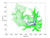
The plan of the Old dam and the reservoir is shown in Figure 3, as it was reproduced with the use of the computer software on the topographic map at 2m contour intervals.
The plan of Figure 3 shows that the Marathon reservoir is getting most of the inflow from two valleys, one in the northeastern part and the other in the northwestern part of the reservoir. These directions give an insight to the planning engineer of where to look for the positioning of the auxiliary dams.
To find the best position for these dams, research was undertaken to discover which positions at the edges of the dam above el. 210m were narrow enough to place a dam with minimum dam volume but maximum reservoir volume.
Proposed eastern and western dams
The positions of the dams chosen are those that block the flow of the Charadros river itself in the west of the watershed, and the flow of the main tributary in the east of the watershed. At these positions, curved-crest concrete dams with radius of curvature of 600m, upstream slope equal to 6.35:1 (height to horizontal) and downstream slope 1.54:1 (height to horizontal) can be positioned.
The crest width of each dam is assumed at 4.5m. With the level of the spillway being 4m lower than the level of the crest of the dam, the width of the horizontal cross section of the dam will be 7.73m, considering the upstream and downstream slopes of the faces of the dam described previously.
After many trials to position the crest of the dam at the most appropriate location and to examine how high the reservoir might be, two dams with their respective reservoirs were decided and named the Eastern dam and Western dam. The maximum levels of the reservoirs are decided from the elevations of certain saddles existing in the topography close to el. 280. In both cases, the saddles do not allow the reservoir level to increase more than the saddle level, unless a saddle dam is provided in each case.
The Eastern dam is positioned at the approximate location x=7950m and y=3700m to block the waters of the Charadros main tributary, while the Western dam is positioned at the approximate location x=5000m and y=3800m to block the waters of the Charadros river itself.
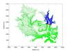
The plan of the Eastern dam and the reservoir is shown in Figure 4. The foundation of the dam is at el. 210m, while the crest of the spillway and the top level of the reservoir are at el. 276m. Assuming the crest of the dam is 4m above the spillway crest, the dam crest level will be at el. 280m. Since the saddle of the topography is at el 278m, 200m upstream of the dam and at the right abutment of the dam, a small saddle dam 2m in height will be needed to create a safe reservoir flood-level and wave control freeboard, with crest at the dam crest level at el. 280m.
The plan of the Western dam and the reservoir is shown in Figure 5. The foundation of the dam is at el. 228m and the crest of the spillway and the top level of the reservoir are at el. 278m. Assuming the crest of the dam 4m above the spillway crest, the crest level of the dam will be at el. 282m. Since the saddle of the topography is at el 279m, 500m upstream from the dam and at the right abutment of the dam, a small saddle dam 3m in height will be needed to create a safe reservoir flood-level and wave control freeboard, with crest at the dam crest level at el. 282m.
The heights of the Eastern and Western dams are shown in Table 1. The heights of the two proposed dams are considered from the ground level and up, while the real foundation of the dams will be down to the rock surface after the overburden is removed. The same will be valid for the two saddle dams that will have total height the height from the ground surface plus the excavation depth for their foundation.
The types of dam considered are concrete dams, which require the least volumes compared to other types of dams. In case other types are needed, earth or rockfill dams can be chosen with larger upstream and downstream slopes. The computer program will then need to be run again to give the new volumes for these dams and the respective reservoirs.
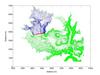
The positions in plan of the three dams and reservoirs are shown in Figure 6. It is seen that the Eastern dam covers the reservoir of the Old dam at a depth of el. 223 (Old reservoir level) minus el. 210 (Eastern dam foundation level on ground surface). This makes a difference of 13m, that will be the submergence of the downstream foot of the Eastern dam within the Old reservoir.
One can see from Figure 6 that the Western dam is at a distance from the reservoir of the Old dam, since the foundation of the dam at el.228 is at a height of el. 228 (Western dam foundation on ground surface) minus el. 223 (Old dam reservoir level). This makes a difference of 5m, which will be the height of the downstream foot of the Western dam above the top level of the Old reservoir.
The arrangement of the dams and reservoirs in Figure 6 show that the Old reservoir can increase by increasing the height of the Old dam by 5 to 10m. This would create an increase of the coastline of the reservoir and continuation of the reservoir to and above the toe of the Western dam. All three reservoirs and the areas of land they cover create an arrangement of reservoirs that can be developed for recreational purposes, either with reservoir levels as shown in Figure 6 or with reservoir levels at higher or lower elevations, according to environmental needs, such as fish and water foul breeding.
Discussion
The characteristics of the three dams, the Old Marathon dam, and the proposed Eastern dam and Western dam are presented in Table 1. The values of Table 1 are the maximum values of the dams placed at the positions shown on Figure 6, while smaller dams and reservoirs can be planned in the same locations, by lowering the levels of the reservoirs.
Other factors that might be considered in the planning of the Eastern and Western dams are the geology of the site and the thickness of the overburden, the agricultural and cattle raising activities at the areas covered by the reservoirs, the existing villages and roads, the telephone and power lines, and mainly the interests for development of the societies living in the vicinity of the reservoirs. The hydrology of the area is not considered a factor, assuming that the mean annual rainfall of the area of 772mm, as considered in the original study of the Marathon reservoir, that corresponds to 95.7Mm3 of precipitation annually. This inflow from the watershed precipitation, plus the inflows from the Yliki and Mornos reservoirs, can be adequately stored to the maximum available storage volume, which is equal to 22.06+42.72+81.67 = 146.45Mm3 in the three reservoirs.
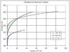
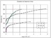
In the planning stage of the two auxiliary reservoirs, the Eastern and the Western reservoir within the Marathon dam watershed, the planning engineer will consider the different factors affecting the planning of the dams in connection to the charts of elevation versus reservoir area of Figure 7. The extent of the reservoir area of the Eastern reservoir is small compared to the two other reservoirs, since the topography is steep to the riverbed of that reservoir, approximately 1:5 (height to horizontal) or 0.2:1 (height to horizontal), and mostly shrub and wooded land will be inundated. The Western reservoir is wider, and it covers approximately the same area of the Eastern reservoir at a height equal to half the height of the Eastern dam. The topography is smoothly sloping to the riverbed at the Western reservoir, with slopes approximately 1:12 (height to horizontal) or 0.08:1 (height to horizontal), and consists mostly of grazing and shrub land.
To define the height of the dams, the planning engineer has to compare the information from Figure 6 and Figure 7 to the maps with scales 1:5,000 and 1:50,000 of the Geographic Military Service of Greece that provide information on the built environment in the areas covered by the reservoirs. If certain features on the topographic maps cannot be transferred or expropriated, then the reservoir level has to be at a lower elevation and the respective reservoir area will be estimated from the chart of Figure 7.
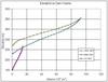
Regarding the economics of building the dam, the planning engineer will use the chart of Figure 8 that shows the elevation versus the volumes of the dams. The Old dam has a volume in the order of 150 x103 m3, while the Eastern and Western dams have almost equal volumes in the order of 900 x103 m3. The Western dam is longer than the Eastern dam at the dam crest level (1350m to 820m), while regarding the heights of the dams it is shorter (54m to 70m). The volume of the dams will be increased based on the required foundation depth for each dam. Also, the cost of the dams that depends mainly on the volume of the dams to the foundation levels, will increase regarding the cost of the grout and drainage curtains and the foundation treatment of the dams. From Fig. 7 the planning engineer can have an indication of the volume of the dam for lower elevations of the dam crest.
The planning engineer will also use the chart on Figure 9, showing the variation of elevation versus the volumes of the reservoirs, to decide on the useful volumes of the reservoirs for different uses. The lower volumes of the reservoirs will be used for the sediments, and will be considered the dead volumes of the reservoirs. After a decision is taken on the extent of the reservoir area and the dam volume, according to the factors mentioned previously, the planning engineer will decide on the levels for each reservoir that will indicate the top of the dead volume, the maximum reservoir level, and the maximum flood level.
The computer software used in this research positions the dams on the topography of Figure 1 and Figure 2, produces the plans of the dams and the reservoirs of Figure 3, Figure 4, Figure 5, and Figure 6, and generates all the numerical values needed for the plotting of the charts of Figure 7, Figure 8, and Figure 9. The computer program used is a convenient tool for the planning engineer, when considering the several factors affecting their planning, since they get accurate plans of the dams and reservoirs, and numerical data along with the plots of the charts indicating the variation of the elevation versus reservoir area, dam volumes and reservoir volumes.
The increase of the storage of the Marathon reservoir by developing the Eastern and Western reservoirs gives the possibility of different uses of water outside water supply, such as recreation and irrigation, and is to the benefit of the residents of the nearby areas for the aesthetics and the environmental development of their region.
Conclusions
The research presented in this paper refers to the Marathon watershed in the northeastern part of Athens, Greece, and develops two new dams and reservoirs with the goal to increase the storage capacity of the Marathon reservoir. The two new dams and reservoirs, named the Eastern and the Western dams, will store water from precipitation, while the old Marathon reservoir will store water both from precipitation and from the interconnected water supply system. The research gives the tools to the planning engineer to examine different heights of the new dams and reservoirs along with different factors restricting parts of the development. The tools to the planning engineer given by this research are the plans of the dams and the reservoirs, and the charts of elevation versus areas of reservoirs, and elevations versus volumes of the dams and reservoirs. The final planning chosen among several alternatives has to benefit the nearby residents, regarding the uses of water, the aesthetics, and environmental development of the region.
TablesTable 1