Straight to the source of seepage
8 December 2005Jim Swaisgood, Jerry Montgomery and Val Kofoed report on the investigative work undertaken to discover the source of seepage at River Reservoir dam in the US
Water seeping through an earthen embankment suggests a number of possible circumstances, and none of them are good. At best, the reservoir owner is losing a valuable commodity. The worst case scenario is that the seepage may be the precursor of dam failure. The first step in addressing a problem with seepage is as obvious as it is difficult: pinpointing its source. In the past, procedures for determining the exact location and nature of seepage points have been both costly and time consuming. Of course, when dam failure is imminent, there is much more than money and time at stake; the efficiency and speed with which engineers can locate the source of seepage may make the difference between a timely fix and catastrophe.
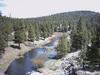
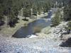
River Reservoir dam is an arched earthen structure on the headwaters of the Little Colorado river. It is located about 24km southwest of Eagar, Arizona, US, and is owned and operated by Round Valley Water Users Association (RVWUA). Based on very limited engineering, the dam was constructed by settlers in 1896 of local materials and without a clay core. Due to recurring sloughing problems, the dam received significant modifications on at least four separate occasions. The embankment consists of clayey soils within a rockfill shell, measuring 335m long with a maximum height of approximately 21.3m and is founded upon basalt bedrock.
In 1996 additional riprap was installed to reduce the original slope of the upstream and downstream faces. A review of the early inspection reports revealed that the left abutment drain was constructed using tabular rocks to create a box-shaped opening over the rock foundation. However, the contacts between these rocks were neither sealed nor grouted. There has been much speculation regarding the original purpose of this drain. Most investigators believe that it was constructed to carry away water that emerges from a perennial spring rumored to exist within the left abutment; it may also have been intended to function as a temporary outlet to the reservoir.
In late March 2004 an unusual amount of water was observed to be seeping from the left-abutment weir box. This seepage contained significantly higher than normal silt content. The path of the seepage was thought to be related to the supposed spring, its associated clay pipe, and the stone-box drainage system. Investigators feared the possibility of imminent dam failure. Emergency personnel were mobilised to the site to monitor and address the situation. RVWUA immediately contacted the State of Arizona, which agreed to fund the investigation and subsequent remediation work. RVWUA also enlisted the services of Turner Collie & Braden (TCB), an AECOM company, which contacted Willowstick Technologies (Willowstick). Working together, TCB and Willowstick were able to assist RVWUA in investigating and resolving the rapidly deteriorating situation.
Aquatrack technology
The manner in which the investigative work was done can only be fully appreciated when understanding how Willowstick’s AquaTrack technology works. AquaTrack uses a low voltage, low amperage, audio-frequency electrical current to energise the groundwater or seepage in question. Electrodes are placed strategically in wells, springs or surface water so as to induce electricity to flow through the groundwater system of interest. Because groundwater is a conductor, the electrical current will follow the path of the groundwater between the electrodes. As it flows through the groundwater the current creates a magnetic field. This magnetic field can be identified and surveyed from the surface using a highly sensitive and specially tuned magnetic receiver. The magnetic receiver measures the specific magnetic field, filters out interference, and amplifies the signal. Repeated measurements are recorded over time to ensure consistent results. The equipment used to measure the magnetic field includes three sensors oriented in orthogonal directions, a data logger used to collect, filter and process the sensor data, a Global Positioning System (GPS) to locate and map the field measurements, and a Windows-based handheld computer to store the GPS and magnetic field data. This equipment is mounted on a surveyor’s pole and can be hand-carried to each measuring station.
The AquaTrack instrument measures the voltage from each of the three sensors located at each measurement station. The measured values correspond to the strength of the magnetic field. For quality control, a base station is established within the survey area. The field strength at the base station is measured at the beginning, middle, and end of each field day. This data is used to identify any changes in the background magnetic field, such as diurnal drift. The magnetic field measurements collected during the survey of the larger region of interest are later normalised to compensate for these effects. The quality of the data is also assured by examining the signal-to-noise ratio in real time, and fluctuations in the data due to natural and man-made phenomena are removed. The horizontal and vertical magnetic field magnitudes and directions can be measured to further define the groundwater or seepage system. The survey data is later normalised to show relative highs and lows in the magnetic field strength. High relative field strengths correspond to higher current flows and represent an increased presence of groundwater.
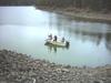
In the case of the River Reservoir dam investigation, one electrode was installed in the lake approximately 244m south of the western abutment and a second was placed in the left abutment weir box, where the high silt content was observed (about 43m downstream of the crest of the dam). These two electrodes were connected by heavy gauge wire and linked to a 400Hz power generator. An electrical current was then induced between the two electrodes. One hundred and seven magnetic measurements were then taken on the upstream and downstream sides of the dam, as well as on the crest. Twenty additional measurements were taken from a boat in the reservoir. Upon completion of the fieldwork, the collected data was then sent back to the lab for interpretation. The measured magnetic field data were processed, contoured, and correlated to other hydrogeologic information. This resulted in an enhanced definition of the extent and preferential flow paths of the seepage. The results of the survey pinpointed the area with the greatest leakage in both the horizontal and the vertical directions.
Mapping seepage
Armed with this data, Willowstick produced maps of the preferential flow paths that existed between the reservoir and the left abutment weir box and its associated drainage system. This information was integral to the comprehensive remedy developed by the geotechnical engineers at TCB. Willowstick personnel mobilised rapidly on short notice and performed the investigation work over a two day period. Preliminary maps were generated on an overnight basis. The final report was presented to TCB within a couple of weeks from completion of the fieldwork.
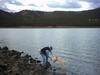
The location of the leak was confirmed through dye tests performed immediately after the magnetic field survey. Three different fluorescent dyes were used for the tracer work, fluorescein (green), eosine (yellow), and rhodamine WT (red). The rhodamine was placed in the middle section of the dam near the old tabular-stone drain. The fluorescein was introduced at a point to the left of where the rhodamine was introduced and the eosine at a point to the right. Less than ten minutes following its introduction, a substantial amount of rhodamine was observed downstream, confirming previous findings and indicating serious seepage problems.
Following Willowstick’s analysis and the subsequent ground proofing, the reservoir was drawn down to a level below the primary area of concern in order to implement temporary remedial measures to eliminate the risk of immediate failure.
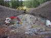
Repair of the embankment began in August 2005 with the excavation of a V-notch cut. This was designed to expose and remove the alleged open stone drain that had been assumed to exist as evidenced by the interpretation of historical records, the AquaTrack survey results and dye studies. Other investigatory techniques such as probing and exploration borings also contributed to the interpretation results. In September of the same year, the foundation level was reached and the excavator encountered an open tunnel in the same location as suspected. The excavation revealed that the construction of the drain consisted of a 0.3m wide by 0.6m high drain, which had been blasted into the basalt bedrock and the sides and top were formed with tabular rock.
At a distance of approximately 32m upstream from the downstream exit of the drain, the opening was blocked with a grouted rock mass that had been constructed in an effort to seal the opening. Based on historical records, this seal was attempted prior to 1920, but was not effective. Just downstream from the seal, a drain channel was found to enter the main drainage tunnel at a sharp angle from the left abutment. This pathway was developed in a natural soil and rock channel under a log platform that had been left in the embankment and then covered with materials that had been placed to stabilise the upstream slope. This slope had been undergoing periodic rapid drawdown sliding from the early 1900s until 1949 when the face was finally constructed with a stable angle. The seepage flow path that was formed by this combination of features was the source of the distinctive right-angle pattern detected by the AquaTrack survey. The speed and accuracy with which the CS-FDM technology generated these results was crucial to the success of subsequent remediation efforts.