The key link in the Waitaki chain
20 September 2010The refurbishment of Benmore hydropower station in New Zealand is on track for completion by January 2011. Johan Hendriks gives more details about the work taking place
Benmore hydropower station is located in the South Island of New Zealand and is the sixth out of a chain of eight power stations on the Waitaki river. At 540MW it is the second largest hydro station in New Zealand in terms of installed capacity and annual generation.
The station provides around 2200GWh annually which is 17% of the energy delivered from Meridian Energy’s power portfolio. Moreover, the station ensures hydrology flexibility for Aviemore and Waitaki power stations and provides essential support services for the operation of the Transpower owned HVDC link. Reduction in the station performance would not only decrease energy output, but also the ability to transfer energy to and from New Zealand’s North Island.
Power supply
The six Francis turbines at Benmore are of an identical hydraulic design and were commissioned between 1965-6. The six generators are each rated at 112.5 MVA. They are capable of running at 100MW at 0.9 pf but are limited to 90MW output due to operational constraints. Currently the total 540MW, 600MVA output of Benmore is provided to Transpower’s 16kV bus which in turn can supply either or both of Pole 1 of the HVDC, or the 220kV grid via Transpower’s two 232MVA transformers (T2 and T5). The bus is normally run split with three generators on each side to limit the fault level. This configuration can be seen in Figure 1. Benmore is used to provide voltage support for Pole 1 of the HVDC link.
Scope of development
Several of the essential operating systems at Benmore are nearing the end of their design/operating life. Significant risks and opportunities were identified in a series of risk management workshops during 2003. The ensuing investigations and remnant life assessments identified components of the generation plant to have either:
• Posed a significant health and safety risk;
• Failed, in respect to no longer operating within the original design performance parameters;
• Reached the end of their supportable economic life, or are due to within the next few years;
•The potential to cause a substantial impact on revenue through reduction in plant and HVDC availability.
Technical and commercial analysis of various refurbishment options were completed to derive the optimum scope and timing of work to maximise benefits from the investment, and ensure an appropriate fit with Meridian’s long term corporate goals and strategies. This led to a business case being presented to the board of directors.
Risks and opportunities
The following risks and opportunities were identified as those which are critical and will be addressed through implementation of the refurbishment project:
Risk mitigation:
• Mitigate the risk of catastrophic equipment failure which has the potential to cause substantial secondary damage to associated plant and pose a risk to operations and maintenance staff.
• Avoid plant becoming unavailable for long periods while parts are being procured or where obsolete repairs are affected.
• Ensure that the plant remains compliant with legislative and regulatory requirements.
• Avoid stranding the assets and constraining generation due to a failure of either pole 1 or the interconnecting or converter transformers.
• Avoid constraining the HVDC as a result of multiple unit outages due to plant and local service failures.
Asset management:
• Implement changes that ensure plant performance targets can be maintained or enhanced through the replacement of ageing assets and/or reconfiguration to provide segregation and diversification of critical systems.
• Implement changes that will ensure future compatibility with Transpower’s proposed HVDC upgrades.
• Support the operational life of Benmore for a further 40 years.
• Ensure that life cycle costs are minimised through avoiding escalating maintenance requirements and costs and minimising the revenue earning impact due to the reduced reliability of ageing assets.
The scope of works for this five-year refurbishment project is extensive and began in January 2006. The following are the main aspects of the project.
Turbine runners
The turbine runners in each of Benmore’s six turbines are the original runners designed and manufactured by Dominion Engineering (now part of General Electric), Ontario, Canada. To the original designer’s credit, the turbines have remained in service continuously from commissioning in 1965-6, except for planned maintenance activities.
Of the six Benmore machines, three have never been completely dismantled whilst three have undergone refurbishment in the mid 1990s. However, the runners on all six machines have required cavitation damage repair every three years, which has resulted in distortion of the runner blades.
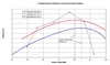
Efficiency testing in 2002 compared the existing runner efficiency to that of the as- commissioned turbines in 1965. From the results it was evident there had been a significant loss in turbine efficiency due, predominantly, to the distortion of the runner blades. An opportunity also existed to further improve station efficiency over and above the original design. This gain was proven following CFD analysis and model testing. The replacement of the runners will eliminate the maintenance burden associated with cavitation repairs through using available advanced design techniques.
The plots in figure 2 show the reduction in turbine efficiency between 1965 and 2002 together with a shift in the peak efficiency point to higher turbine loads. The shift in peak efficiency load has the effect of decreasing the time when the turbine is operating around its best efficiency. The above comparison was the basis for implementing a runner and associated turbine components replacement programme at Benmore.
Subsequent tendering for replacement turbine runners returned a large range of turbine enhancement options ranging from replacing the turbine runners only, through to replacing the runners and wicket gates together with modifying the stay vane profiles and turbine flow passage shape. All of the above options had an increased cost together with an increase in turbine efficiency, but following extensive evaluation of the bid options from various turbine manufacturers, a replacement runner and wicket gate option supplied by Toshiba was deemed to give the best return to Meridian.
16 kV generator Circuit Breakers
The 16kV circuit breakers provide a critical protection function, but are nearing the end of their life (normal life expectance of a circuit breaker is 35 years according to international statistics). Forced outages are becoming more frequent and severe and present a significant risk to plant, personnel and the station availability.
The 16kV circuit breakers, designated CB1 to CB6, connecting the generators to the main bus are Brown Boveri model DB 20RC 1500/1 single phase air breaker type. They have a 5000A load rating with a fault rating of 2500MVA. They are originally-installed equipment and although routine maintenance is conducted they have not been refurbished or upgraded since commissioning.
Based on analysis of historical forced outage data and discussion with maintenance staff it was estimated that the circuit breakers would reach the end of their operational life by 2009. The acquisition of spare parts is difficult and lengthy – a breaker failure in February 2003 caused a six-week forced outage which resulted in a six-fold increase in annual forced outage factors and 5% reduction in annual availability for that year. The types of faults occurring are increasingly due to age deterioration of components. Spare parts are very expensive to obtain and it is difficult to determine what parts to hold as the age-related failures are hard to predict.
Efforts have been made to limit the number of circuit breaker operations in recent years in an attempt to reduce degradation by encouraging operators to run the units on tail water depressed mode when not required, rather than stop the units. This is not an adequate long-term solution as running the units in this mode is not an efficient way to use water. To maintain adequate service in the short term, it is critical to address the issue of spare parts availability as soon as possible.
The circuit breakers will be replaced with ABB HEC-80S SF6 circuit breakers, 8500A rated continuous current, 80 kA rated short circuit breaking current.
Excitation and automatic voltage regulation
The excitation system suffers from age related faults and requires an increasing maintenance effort. The equipment is based on 1950s technology that is no longer supported and future failures will result in protracted unit outages due to the reduced availability of spare parts and maintenance expertise. The market driven increasing number of stop/starts will also further escalate the rate of deterioration.
Maintaining power quality and compliance with Electricity Governance Rules have become increasingly difficult and opportunities exist for improving voltage support performance and reducing synchronising time with modern equipment. The excitation upgrade will increase the asset life and maintain operational efficiency and availability by reducing the risk of failure of obsolete ageing equipment.
This project will replace the electromechanical AVR with digital controlled types and replace the existing motor driven Amplidynes with controlled bridge rectifiers. The exciter field supply will be from new unit excitation transformers. The existing generator slip rings and brush gear will be retained and DC interrupting devices will be installed. Grid power system stabilisers will also be installed.
The excitation project will:
• Extend the life of the excitation and AVR by 25 years.
• Reduce the risk of failure of the aging excitation and AVR system.
• Improve spares availability.
• Reduce the maintenance requirement on the system by 50%.
• Not impact the current generator capability with respect to achieving 100 MW output, or the ability to interface to existing voltage control signals.
The excitation components are supplied by Basler Electric from France and installed by Transfield Services New Zealand. The new excitation systems are commissioned concurrently with the commissioning of the new turbine runners.
Mechanical refurbishment
In the late 1990s units 2, 3 and 6 underwent a mechanical refurbishment to address the deteriorated state of critical items of plant. The remaining three units now require refurbishment to maintain target levels of station availability and minimise lifecycle O&M costs.
This work includes all systems associated with each hydro unit (eg governors, stator coolers, bearings, brakes, rotors, etc), but excludes the stators. The stators will have at least ten years remaining life left and where appropriate will undo selected re-wedgings of the windings.
3.3kV and 415V local service supplies
The lack of diversity and segregation of the essential supplies presents a significant risk of multiple unit or even whole station forced outages, particularly as the component parts are reaching the end of their operational life. There was also a requirement to maintain the equipment in a live state, which does not align with safe working practice and presented a health and safety risk that could result in a fatality.
The existing configuration relies on the interconnecting transformers (T2 and T5) and the HVDC Pole 1 to be available to avoid constraining the Benmore power station. The existing Pole 1 will be decommissioned by 2012 and replaced with a static converter pole supplied from the 220 kV grid. This has forced Meridian to reconfigure the grid injection point.
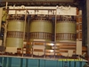
The existing interconnecting transformers and their associated 16 kV circuit breakers are at the end of their life and have a high likelihood of failure. So as part of the reconfiguration, Meridian is replacing the interconnecting transformers and adding extra transformer capacity.
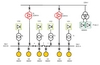
This project will install three new 225MVA winding transformers through which the generators G1 to G6 will connect directly to the 220kV grid by means of a strung bus. The proposed configuration is shown in Figure 3. The two low voltage windings in each transformer are loosely coupled to reduce fault levels. This allows for more economical generator circuit breakers to be used.
All 16 kV connections are made by isolated phase bus duct. This provides a fully phase segregated configuration, a high reliability and low maintenance. The bus duct will be supplied by Alfa Standard in Italy.
Project progress
The project is well underway with four of the six units refurbished. The excitation and local services upgrade have been completed, one new 225 MVA transformer installed and supply contracts for isolated phase bus duct and circuit breakers awarded.
Once complete, Benmore will provide a reliable generation capacity of 540MW at an increased efficiency. It will continue supporting the HVDC link to New Zealand’s North Island.
The author is Johan Hendriks, Strategic Electrical Engineer with Meridian Energy Ltd. New Zealand. Email: Johan.hendriks@meridian.co.nz
This article is based on two papers originally presented at the EEA conference in New Zealand. The conference technical papers are available from Electricity Engineers’ Association, New Zealand www.eea.co.nz
TablesThe Waitaki system